Chapter 1 Hardware Preparation and Installation
SCON Header (J7)
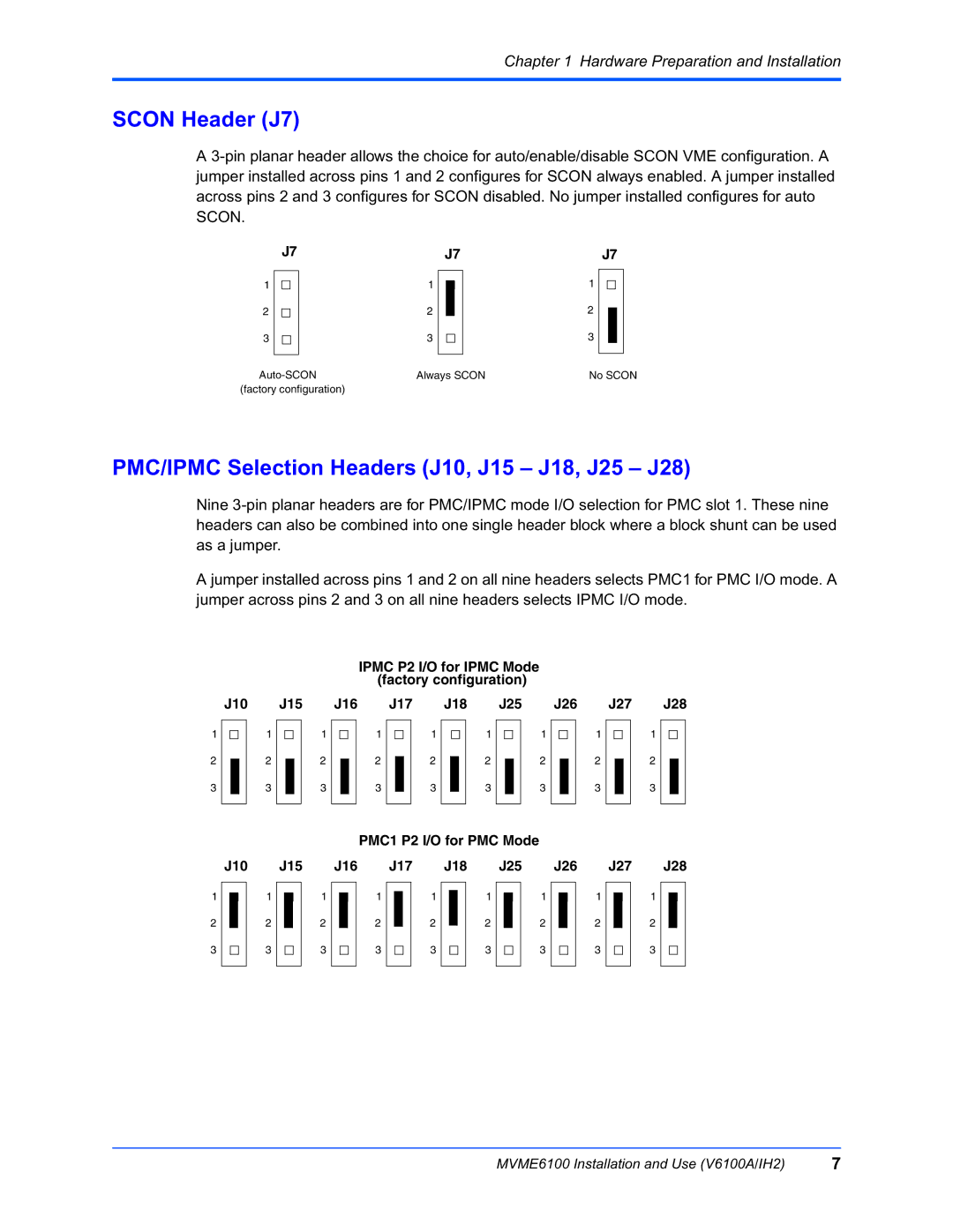
A
| J7 |
| J7 |
| J7 | |||||||
1 |
|
| 1 |
|
|
|
| 1 |
|
|
|
|
|
|
|
|
|
|
|
|
|
| |||
|
|
|
| |||||||||
2 |
|
| 2 |
|
|
|
| 2 |
|
|
|
|
|
|
|
|
|
|
|
|
|
| |||
3 |
|
| 3 |
|
|
|
| 3 |
|
|
|
|
|
|
|
|
|
|
|
|
|
|
|
|
|
Always SCON | No SCON | |||||||||||
(factory configuration)
PMC/IPMC Selection Headers (J10, J15 – J18, J25 – J28)
Nine
A jumper installed across pins 1 and 2 on all nine headers selects PMC1 for PMC I/O mode. A jumper across pins 2 and 3 on all nine headers selects IPMC I/O mode.
IPMC P2 I/O for IPMC Mode
|
|
|
|
|
|
|
|
|
|
|
|
|
|
| (factory configuration) |
|
|
|
|
|
|
|
|
|
|
|
|
|
| ||||||||||||||
| J10 |
| J15 |
| J16 |
| J17 |
| J18 |
| J25 |
| J26 |
| J27 |
| J28 | ||||||||||||||||||||||||||
1 |
|
|
|
| 1 |
|
|
|
| 1 |
|
|
|
| 1 |
|
|
|
| 1 |
|
|
|
| 1 |
|
|
|
| 1 |
|
|
|
| 1 |
|
|
|
| 1 |
|
|
|
|
|
|
|
|
|
|
|
|
|
|
|
|
|
|
|
|
|
|
|
|
|
|
|
|
|
|
|
|
|
|
|
|
|
| |||||||||
2 |
|
|
|
| 2 |
|
|
|
| 2 |
|
|
|
| 2 |
|
|
|
| 2 |
|
|
|
| 2 |
|
|
|
| 2 |
|
|
|
| 2 |
|
|
|
| 2 |
|
|
|
|
|
|
|
|
|
|
|
|
|
|
|
|
|
|
|
| |||||||||||||||||||||||||||
|
|
|
|
|
|
|
|
|
| ||||||||||||||||||||||||||||||||||
3 |
|
|
|
| 3 |
|
|
|
| 3 |
|
|
|
| 3 |
|
|
|
| 3 |
|
|
|
| 3 |
|
|
|
| 3 |
|
|
|
| 3 |
|
|
|
| 3 |
|
|
|
|
|
|
|
|
|
|
|
|
|
|
|
|
|
|
|
|
|
|
|
|
|
|
|
|
|
|
|
|
|
|
|
|
|
|
|
|
|
|
|
|
|
|
|
|
|
|
|
|
|
|
|
|
|
|
|
|
| PMC1 P2 I/O for PMC Mode |
|
|
|
|
|
|
|
|
|
|
|
|
|
| ||||||||||||||
| J10 |
| J15 |
| J16 |
| J17 |
| J18 |
| J25 |
| J26 |
| J27 |
| J28 | |||||||||||||||||||||||||
1 |
|
|
|
| 1 |
|
|
|
| 1 |
|
|
| 1 |
|
|
|
| 1 |
|
|
|
| 1 |
|
|
|
| 1 |
|
|
|
| 1 |
|
|
|
| 1 |
|
|
|
|
|
|
|
|
|
|
|
|
|
|
|
|
|
|
|
|
|
|
|
|
|
|
|
|
|
|
|
|
|
|
|
|
| |||||||||
|
|
|
|
|
|
|
|
|
|
|
|
|
|
|
|
|
|
|
|
|
|
|
|
|
|
|
|
|
|
|
|
|
| |||||||||
|
|
|
|
|
|
|
|
|
| |||||||||||||||||||||||||||||||||
2 |
|
|
|
| 2 |
|
|
|
| 2 |
|
|
| 2 |
|
|
|
| 2 |
|
|
|
| 2 |
|
|
|
| 2 |
|
|
|
| 2 |
|
|
|
| 2 |
|
|
|
3 |
|
|
|
| 3 |
|
|
|
| 3 |
|
|
| 3 |
|
|
|
| 3 |
|
|
|
| 3 |
|
|
|
| 3 |
|
|
|
| 3 |
|
|
|
| 3 |
|
|
|
|
|
|
|
|
|
|
|
|
|
|
|
|
|
|
|
|
|
|
|
|
|
|
|
|
|
|
|
|
|
|
|
|
|
|
|
|
|
|
|
|
|
|
MVME6100 Installation and Use (V6100A/IH2) | 7 |
