Chapter 4 Functional Description
COM1 is an RS232 port and the TTL- level signals are routed through appropriate
PCI Mezzanine Card Slots
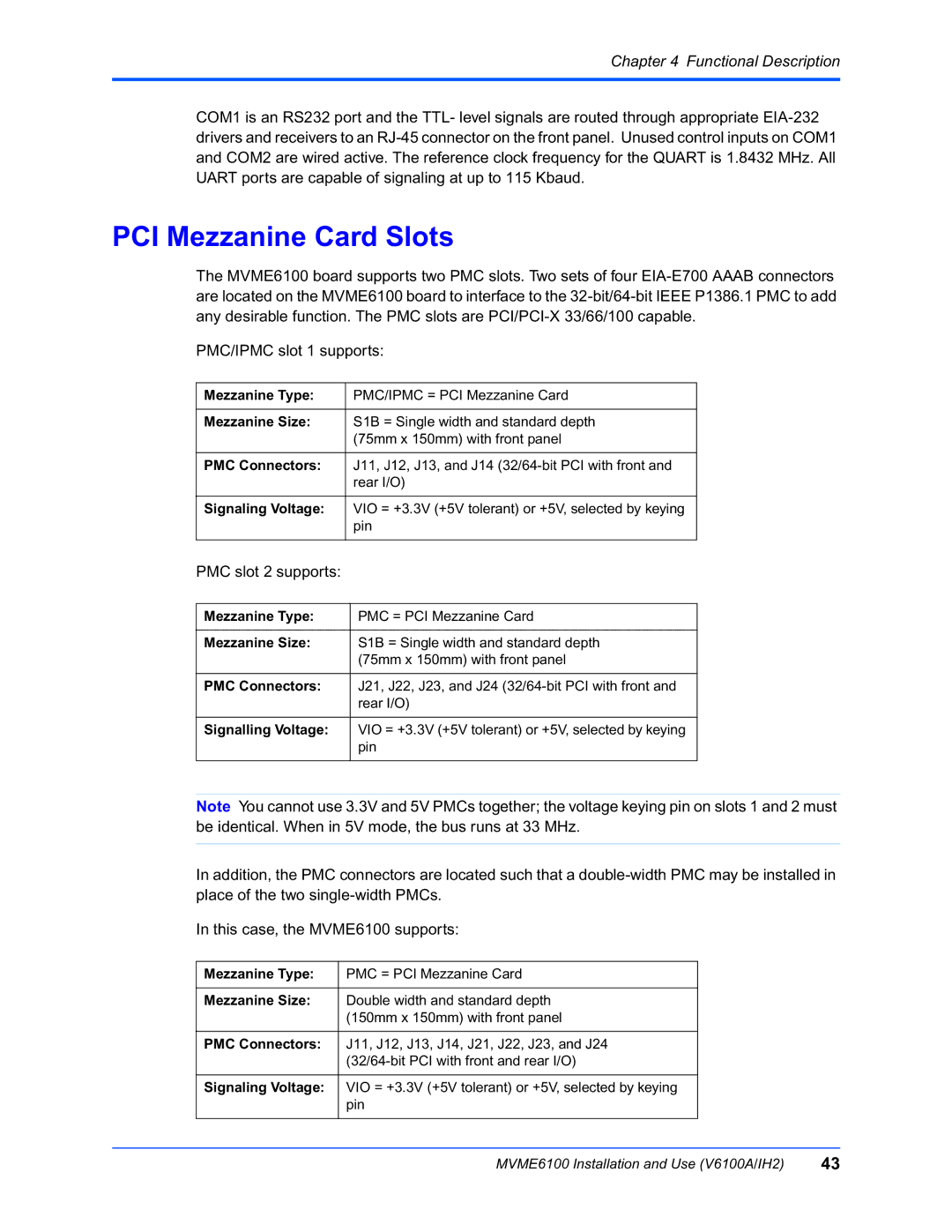
The MVME6100 board supports two PMC slots. Two sets of four
PMC/IPMC slot 1 supports:
Mezzanine Type: | PMC/IPMC = PCI Mezzanine Card |
|
|
Mezzanine Size: | S1B = Single width and standard depth |
| (75mm x 150mm) with front panel |
|
|
PMC Connectors: | J11, J12, J13, and J14 |
| rear I/O) |
|
|
Signaling Voltage: | VIO = +3.3V (+5V tolerant) or +5V, selected by keying |
| pin |
|
|
PMC slot 2 supports:
Mezzanine Type: | PMC = PCI Mezzanine Card |
|
|
Mezzanine Size: | S1B = Single width and standard depth |
| (75mm x 150mm) with front panel |
|
|
PMC Connectors: | J21, J22, J23, and J24 |
| rear I/O) |
|
|
Signalling Voltage: | VIO = +3.3V (+5V tolerant) or +5V, selected by keying |
| pin |
|
|
Note You cannot use 3.3V and 5V PMCs together; the voltage keying pin on slots 1 and 2 must be identical. When in 5V mode, the bus runs at 33 MHz.
In addition, the PMC connectors are located such that a
In this case, the MVME6100 supports:
Mezzanine Type: | PMC = PCI Mezzanine Card |
|
|
Mezzanine Size: | Double width and standard depth |
| (150mm x 150mm) with front panel |
|
|
PMC Connectors: | J11, J12, J13, J14, J21, J22, J23, and J24 |
| |
|
|
Signaling Voltage: | VIO = +3.3V (+5V tolerant) or +5V, selected by keying |
| pin |
|
|
MVME6100 Installation and Use (V6100A/IH2) | 43 |
