Chapter 5 Pin Assignments
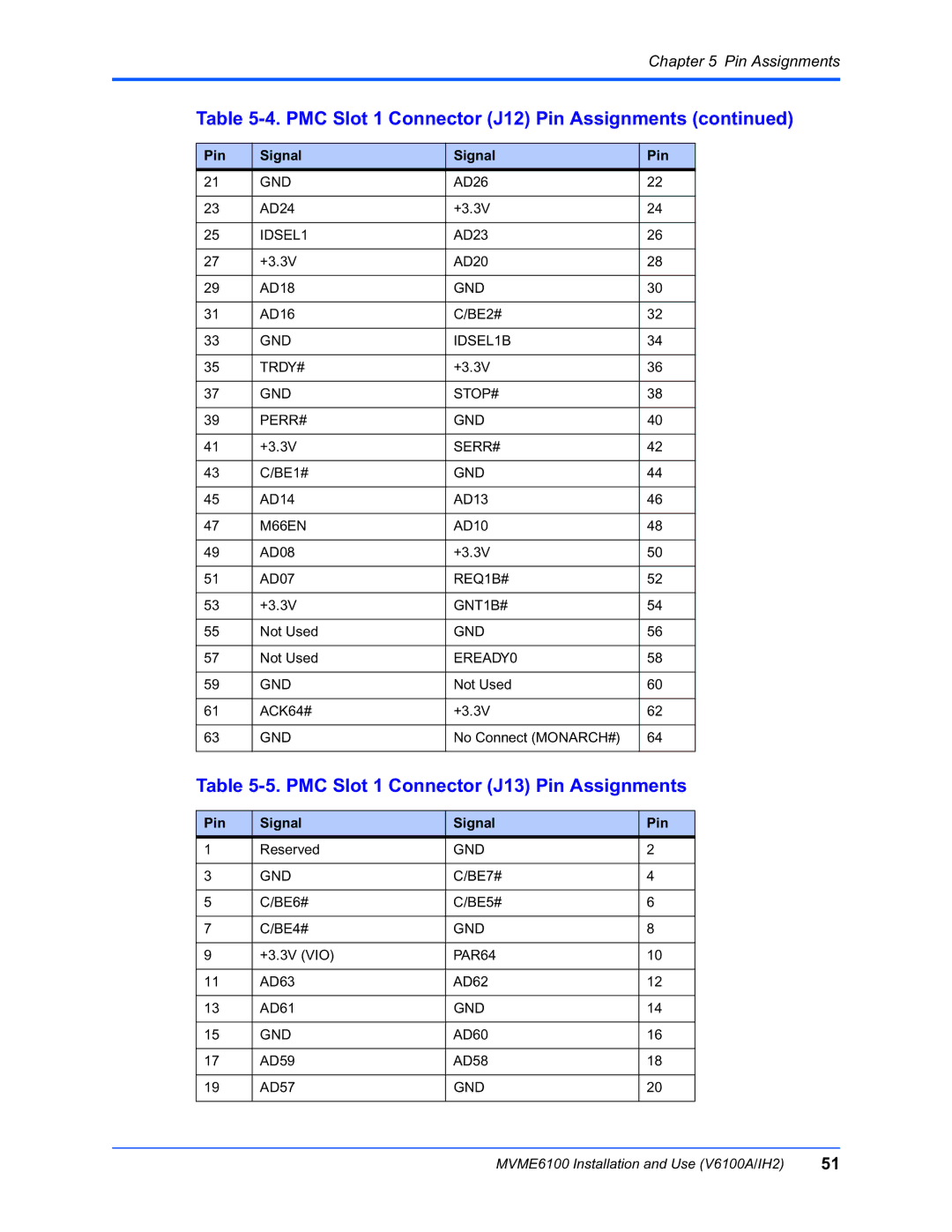
Table 5-4. PMC Slot 1 Connector (J12) Pin Assignments (continued)
Pin | Signal | Signal | Pin |
21 | GND | AD26 | 22 |
|
|
|
|
23 | AD24 | +3.3V | 24 |
|
|
|
|
25 | IDSEL1 | AD23 | 26 |
|
|
|
|
27 | +3.3V | AD20 | 28 |
|
|
|
|
29 | AD18 | GND | 30 |
|
|
|
|
31 | AD16 | C/BE2# | 32 |
|
|
|
|
33 | GND | IDSEL1B | 34 |
|
|
|
|
35 | TRDY# | +3.3V | 36 |
|
|
|
|
37 | GND | STOP# | 38 |
|
|
|
|
39 | PERR# | GND | 40 |
|
|
|
|
41 | +3.3V | SERR# | 42 |
|
|
|
|
43 | C/BE1# | GND | 44 |
|
|
|
|
45 | AD14 | AD13 | 46 |
|
|
|
|
47 | M66EN | AD10 | 48 |
|
|
|
|
49 | AD08 | +3.3V | 50 |
|
|
|
|
51 | AD07 | REQ1B# | 52 |
|
|
|
|
53 | +3.3V | GNT1B# | 54 |
|
|
|
|
55 | Not Used | GND | 56 |
|
|
|
|
57 | Not Used | EREADY0 | 58 |
|
|
|
|
59 | GND | Not Used | 60 |
|
|
|
|
61 | ACK64# | +3.3V | 62 |
|
|
|
|
63 | GND | No Connect (MONARCH#) | 64 |
|
|
|
|
Table 5-5. PMC Slot 1 Connector (J13) Pin Assignments
Pin | Signal | Signal | Pin |
1 | Reserved | GND | 2 |
|
|
|
|
3 | GND | C/BE7# | 4 |
|
|
|
|
5 | C/BE6# | C/BE5# | 6 |
|
|
|
|
7 | C/BE4# | GND | 8 |
|
|
|
|
9 | +3.3V (VIO) | PAR64 | 10 |
|
|
|
|
11 | AD63 | AD62 | 12 |
|
|
|
|
13 | AD61 | GND | 14 |
|
|
|
|
15 | GND | AD60 | 16 |
|
|
|
|
17 | AD59 | AD58 | 18 |
|
|
|
|
19 | AD57 | GND | 20 |
|
|
|
|
MVME6100 Installation and Use (V6100A/IH2) | 51 |