|
|
|
|
| Chapter 5 Pin Assignments | |
|
|
|
|
|
|
|
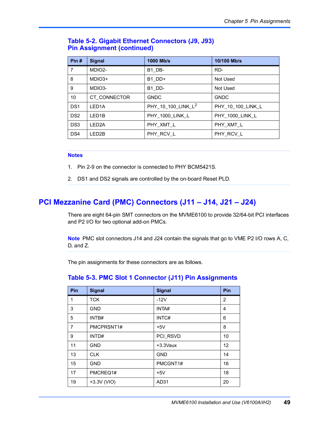
| Table |
|
| |||
| Pin Assignment (continued) |
|
| |||
|
|
|
|
|
|
|
| Pin # | Signal | 1000 Mb/s |
| 10/100 Mb/s |
|
| 7 | MDIO2- | B1_DB- |
| RD- |
|
|
|
|
|
|
|
|
| 8 | MDIO3+ | B1_DD+ |
| Not Used |
|
|
|
|
|
|
|
|
| 9 | MDIO3- | B1_DD- |
| Not Used |
|
|
|
|
|
|
|
|
| 10 | CT_CONNECTOR | GNDC |
| GNDC |
|
|
|
|
|
|
|
|
| DS1 | LED1A | PHY_10_100_LINK_L2 |
| PHY_10_100_LINK_L |
|
| DS2 | LED1B | PHY_1000_LINK_L |
| PHY_1000_LINK_L |
|
|
|
|
|
|
|
|
| DS3 | LED2A | PHY_XMT_L |
| PHY_XMT_L |
|
|
|
|
|
|
|
|
| DS4 | LED2B | PHY_RCV_L |
| PHY_RCV_L |
|
|
|
|
|
|
|
|
Notes
1.Pin
2.DS1 and DS2 signals are controlled by the
PCI Mezzanine Card (PMC) Connectors (J11 – J14, J21 – J24)
There are eight
Note PMC slot connectors J14 and J24 contain the signals that go to VME P2 I/O rows A, C, D, and Z.
The pin assignments for these connectors are as follows.
Table 5-3. PMC Slot 1 Connector (J11) Pin Assignments
Pin | Signal | Signal | Pin |
1 | TCK | 2 | |
|
|
|
|
3 | GND | INTA# | 4 |
|
|
|
|
5 | INTB# | INTC# | 6 |
|
|
|
|
7 | PMCPRSNT1# | +5V | 8 |
|
|
|
|
9 | INTD# | PCI_RSVD | 10 |
|
|
|
|
11 | GND | +3.3Vaux | 12 |
|
|
|
|
13 | CLK | GND | 14 |
|
|
|
|
15 | GND | PMCGNT1# | 16 |
|
|
|
|
17 | PMCREQ1# | +5V | 18 |
|
|
|
|
19 | +3.3V (VIO) | AD31 | 20 |
|
|
|
|
MVME6100 Installation and Use (V6100A/IH2) | 49 |