Chapter 1 Hardware Preparation and Installation
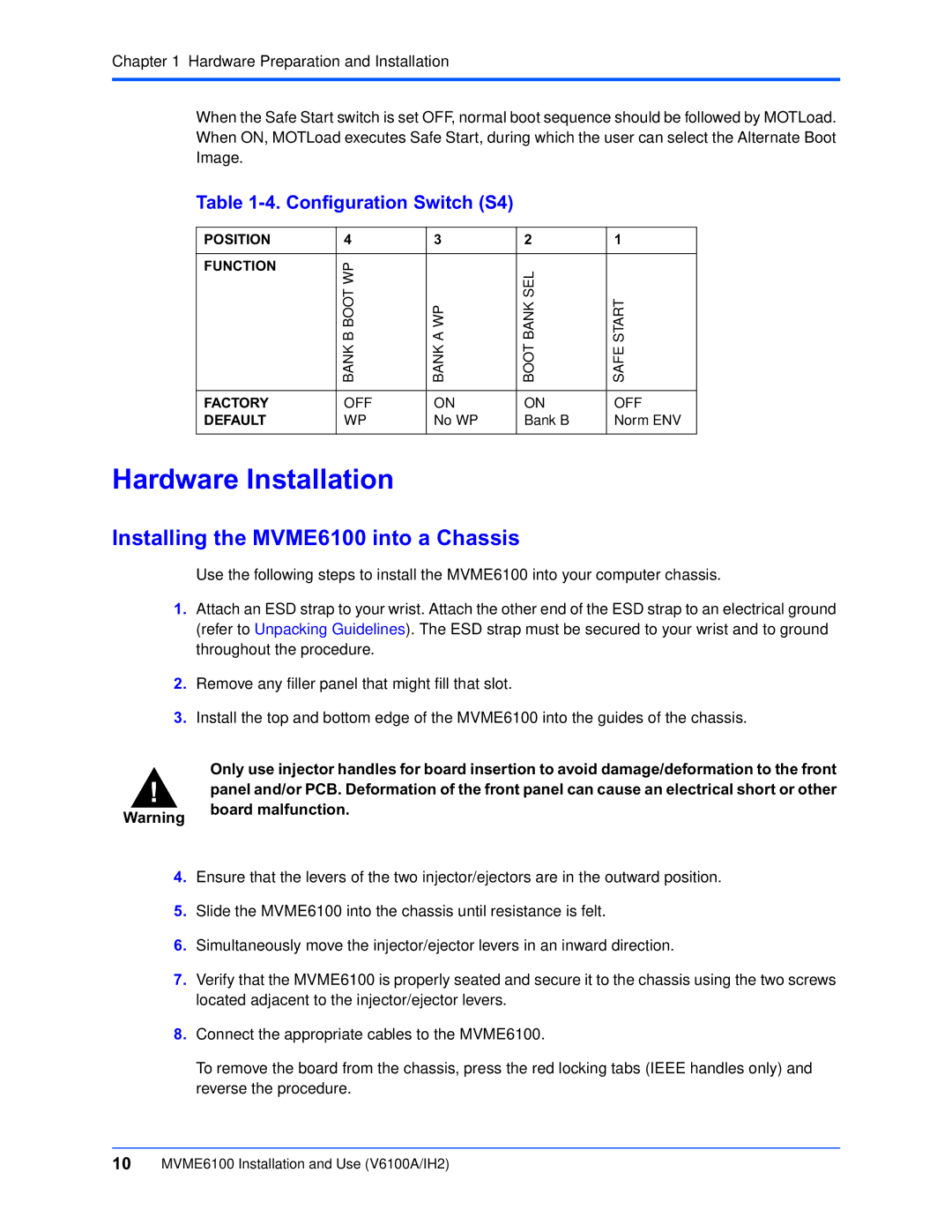
When the Safe Start switch is set OFF, normal boot sequence should be followed by MOTLoad. When ON, MOTLoad executes Safe Start, during which the user can select the Alternate Boot Image.
Table 1-4. Configuration Switch (S4)
POSITION | 4 | 3 | 2 | 1 |
|
|
|
|
|
FUNCTION | B BOOT WP |
| BANK SEL |
|
| A WP | START | ||
| BANK | BANK | BOOT | SAFE |
|
|
|
|
|
FACTORY | OFF | ON | ON | OFF |
DEFAULT | WP | No WP | Bank B | Norm ENV |
|
|
|
|
|
Hardware Installation
Installing the MVME6100 into a Chassis
Use the following steps to install the MVME6100 into your computer chassis.
1.Attach an ESD strap to your wrist. Attach the other end of the ESD strap to an electrical ground (refer to Unpacking Guidelines). The ESD strap must be secured to your wrist and to ground throughout the procedure.
2.Remove any filler panel that might fill that slot.
3.Install the top and bottom edge of the MVME6100 into the guides of the chassis.
Only use injector handles for board insertion to avoid damage/deformation to the front
!panel and/or PCB. Deformation of the front panel can cause an electrical short or other
Warning | board malfunction. |
|
4.Ensure that the levers of the two injector/ejectors are in the outward position.
5.Slide the MVME6100 into the chassis until resistance is felt.
6.Simultaneously move the injector/ejector levers in an inward direction.
7.Verify that the MVME6100 is properly seated and secure it to the chassis using the two screws located adjacent to the injector/ejector levers.
8.Connect the appropriate cables to the MVME6100.
To remove the board from the chassis, press the red locking tabs (IEEE handles only) and reverse the procedure.
10MVME6100 Installation and Use (V6100A/IH2)
