Reference Guide for the Model XM128 ISDN Digital Modem
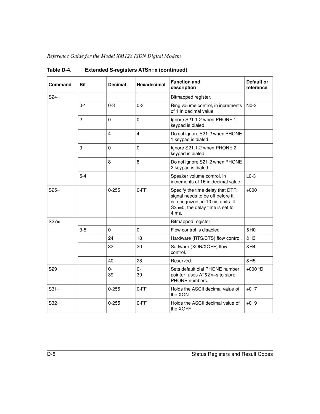
Table | Extended |
| ||||
|
|
|
|
|
| |
Command | Bit | Decimal | Hexadecimal | Function and | Default or | |
description | reference | |||||
|
|
|
| |||
|
|
|
|
|
| |
S24= |
|
|
| Bitmapped register. |
| |
|
|
|
|
|
| |
| Ring volume control, in increments | |||||
|
|
|
| of 1 in decimal value |
| |
|
|
|
|
|
| |
| 2 | 0 | 0 | Ignore |
| |
|
|
|
| keypad is dialed. |
| |
|
|
|
|
|
| |
|
| 4 | 4 | Do not ignore |
| |
|
|
|
| 1 keypad is dialed. |
| |
|
|
|
|
|
| |
| 3 | 0 | 0 | Ignore |
| |
|
|
|
| keypad is dialed. |
| |
|
|
|
|
|
| |
|
| 8 | 8 | Do not ignore |
| |
|
|
|
| 2 keypad is dialed. |
| |
|
|
|
|
|
| |
|
|
| Speaker volume control, in | |||
|
|
|
| increments of 16 in decimal value |
| |
|
|
|
|
|
| |
S25= |
| Specify the time delay that DTR | +000 | |||
|
|
|
| signal needs to be off before it |
| |
|
|
|
| is recognized, in 10 ms units. If |
| |
|
|
|
| S25=0, the delay time is set to |
| |
|
|
|
| 4 ms. |
| |
|
|
|
|
|
| |
S27= |
|
|
| Bitmapped register |
| |
|
|
|
|
|
| |
| 0 | 0 | Flow control is disabled. | &H0 | ||
|
|
|
|
|
| |
|
| 24 | 18 | Hardware (RTS/CTS) flow control. | &H3 | |
|
|
|
|
|
| |
|
| 32 | 20 | Software (XON/XOFF) flow | &H4 | |
|
|
|
| control. |
| |
|
|
|
|
|
| |
|
| 40 | 28 | Reserved. | &H5 | |
|
|
|
|
|
| |
S29= |
| 0- | 0- | Sets default dial PHONE number | +000 *D | |
|
| 39 | 39 | pointer; uses AT&Zn=s to store |
| |
|
|
|
| PHONE numbers. |
| |
|
|
|
|
|
| |
S31= |
| Holds the ASCII decimal value of | +017 | |||
|
|
|
| the XON. |
| |
|
|
|
|
|
| |
S32= |
| Holds the ASCII decimal value of | +019 | |||
|
|
|
| the XOFF. |
| |
|
|
|
|
|
| |
Status Registers and Result Codes |