Reference Guide for the Model XM128 ISDN Digital Modem
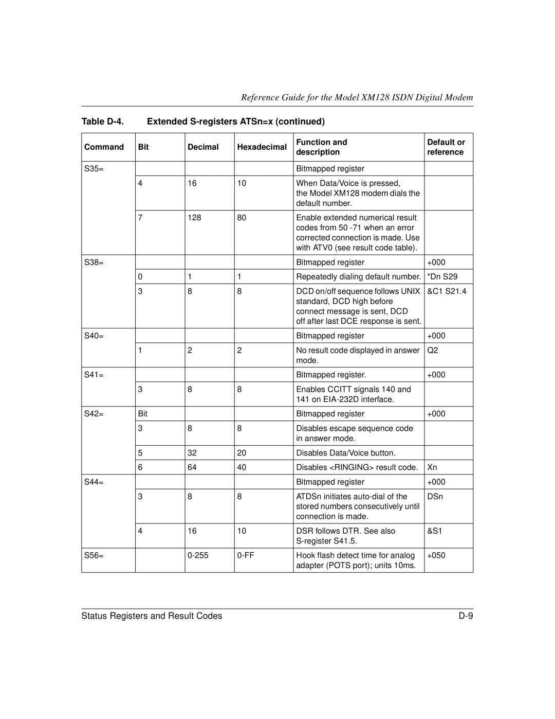
Table | Extended |
| ||||
|
|
|
|
|
| |
Command | Bit | Decimal | Hexadecimal | Function and | Default or | |
description | reference | |||||
|
|
|
| |||
|
|
|
|
|
| |
S35= |
|
|
| Bitmapped register |
| |
|
|
|
|
|
| |
| 4 | 16 | 10 | When Data/Voice is pressed, |
| |
|
|
|
| the Model XM128 modem dials the |
| |
|
|
|
| default number. |
| |
|
|
|
|
|
| |
| 7 | 128 | 80 | Enable extended numerical result |
| |
|
|
|
| codes from 50 |
| |
|
|
|
| corrected connection is made. Use |
| |
|
|
|
| with ATV0 (see result code table). |
| |
|
|
|
|
|
| |
S38= |
|
|
| Bitmapped register | +000 | |
|
|
|
|
|
| |
| 0 | 1 | 1 | Repeatedly dialing default number. | *Dn S29 | |
|
|
|
|
|
| |
| 3 | 8 | 8 | DCD on/off sequence follows UNIX | &C1 S21.4 | |
|
|
|
| standard, DCD high before |
| |
|
|
|
| connect message is sent, DCD |
| |
|
|
|
| off after last DCE response is sent. |
| |
|
|
|
|
|
| |
S40= |
|
|
| Bitmapped register | +000 | |
|
|
|
|
|
| |
| 1 | 2 | 2 | No result code displayed in answer | Q2 | |
|
|
|
| mode. |
| |
|
|
|
|
|
| |
S41= |
|
|
| Bitmapped register. | +000 | |
|
|
|
|
|
| |
| 3 | 8 | 8 | Enables CCITT signals 140 and |
| |
|
|
|
| 141 on |
| |
|
|
|
|
|
| |
S42= | Bit |
|
| Bitmapped register | +000 | |
|
|
|
|
|
| |
| 3 | 8 | 8 | Disables escape sequence code |
| |
|
|
|
| in answer mode. |
| |
|
|
|
|
|
| |
| 5 | 32 | 20 | Disables Data/Voice button. |
| |
|
|
|
|
|
| |
| 6 | 64 | 40 | Disables <RINGING> result code. | Xn | |
|
|
|
|
|
| |
S44= |
|
|
| Bitmapped register | +000 | |
|
|
|
|
|
| |
| 3 | 8 | 8 | ATDSn initiates | DSn | |
|
|
|
| stored numbers consecutively until |
| |
|
|
|
| connection is made. |
| |
|
|
|
|
|
| |
| 4 | 16 | 10 | DSR follows DTR. See also | &S1 | |
|
|
|
|
| ||
|
|
|
|
|
| |
S56= |
| Hook flash detect time for analog | +050 | |||
|
|
|
| adapter (POTS port); units 10ms. |
| |
|
|
|
|
|
| |
Status Registers and Result Codes |