Reference Guide for the Model XM128 ISDN Digital Modem
Rear Panel
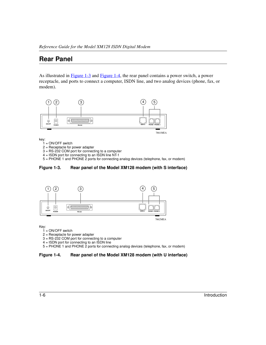
As illustrated in Figure
1 | 2 | 3 | 4 | 5 |
ON/OFF |
| PHONE 1 PHONE 2 | ||
POWER | ||||
|
|
7861MEA
key:
1 = ON/OFF switch
2 = Receptacle for power adapter
3 =
5 = PHONE 1 and PHONE 2 ports for connecting analog devices (telephone, fax, or modem)
Figure 1-3. Rear panel of the Model XM128 modem (with S interface)
1 | 2 | 3 | 4 | 5 |
ON/OFF |
| PHONE 1 PHONE 2 | ||
POWER | ||||
|
|
7862MEA
Key:
1 = ON/OFF switch
2 = Receptacle for power adapter
3 =
5 = PHONE 1 and PHONE 2 ports for connecting analog devices (telephone, fax, or modem)
Figure 1-4. Rear panel of the Model XM128 modem (with U interface)
Introduction |