Reference Guide for the Model XM128 ISDN Digital Modem
1 | 2 | 3 | 4 |
|
|
| U | INTERFACE |
|
|
|
|
|
|
|
|
|
|
|
|
|
|
|
|
|
|
|
|
|
|
| |||
|
|
|
|
|
|
|
|
|
|
|
|
|
|
|
|
|
|
| ||||||||||||
|
|
|
|
| 128Kpbs ISDN Digital Modem |
|
|
|
|
|
|
|
|
|
|
|
|
|
| |||||||||||
|
|
|
|
|
|
|
|
|
|
|
|
|
|
|
|
|
|
|
|
|
|
|
|
|
|
|
|
|
|
|
|
|
|
|
|
|
|
|
|
|
|
|
|
|
|
|
|
|
|
|
|
|
|
|
|
|
|
|
|
|
|
PWR |
|
|
|
| D B1 B2 AA CP |
| DTR DSR RTS CTS TD RD | |||||||||||||||||||||||
|
|
|
|
|
|
|
|
|
|
| ISDN |
|
|
|
|
| COM | |||||||||||||
MODELXM128
1 2
7847MEA
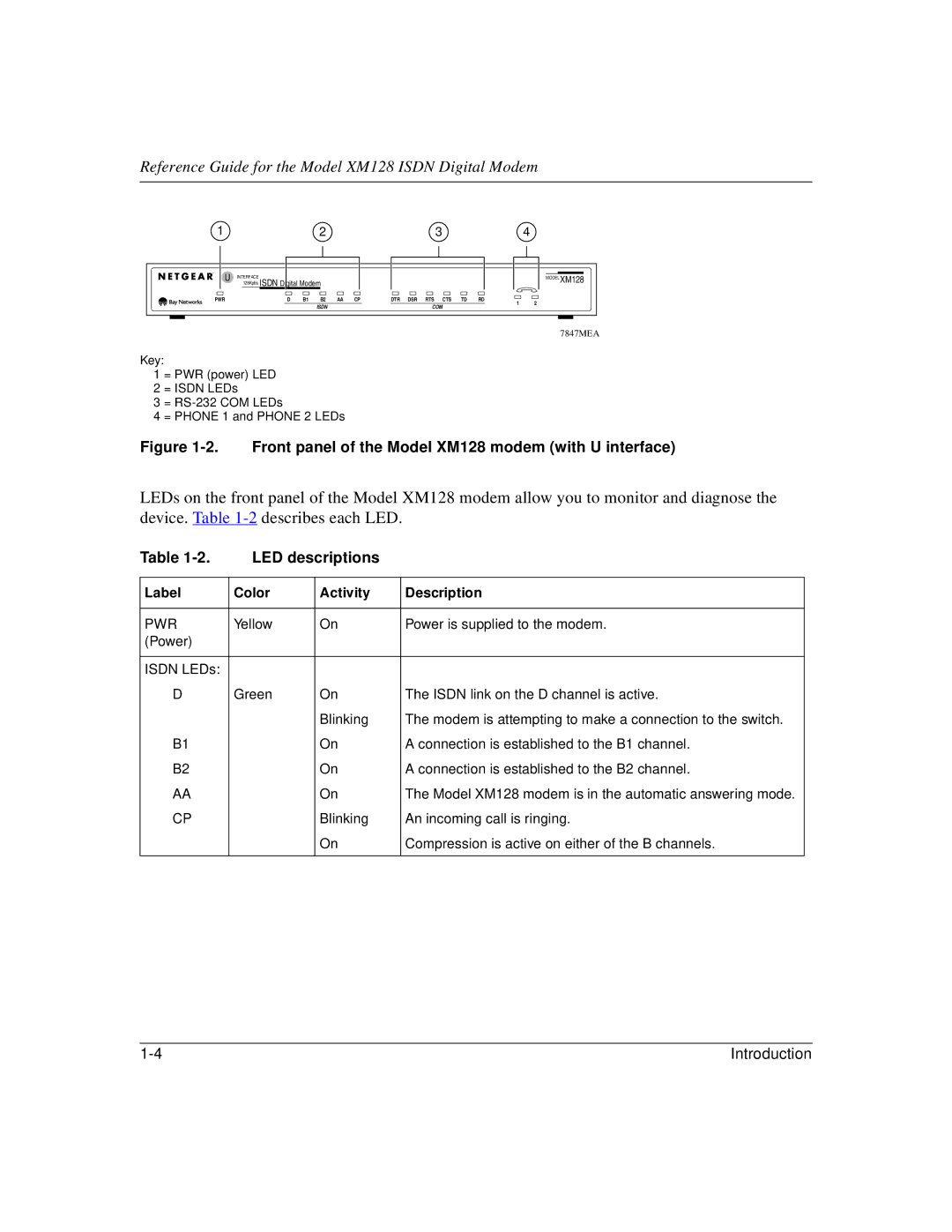
Key:
1 = PWR (power) LED
2 = ISDN LEDs
3=
4= PHONE 1 and PHONE 2 LEDs
Figure 1-2. Front panel of the Model XM128 modem (with U interface)
LEDs on the front panel of the Model XM128 modem allow you to monitor and diagnose the device. Table
Table | LED descriptions |
| |
|
|
|
|
Label | Color | Activity | Description |
|
|
|
|
PWR | Yellow | On | Power is supplied to the modem. |
(Power) |
|
|
|
|
|
|
|
ISDN LEDs: |
|
|
|
D | Green | On | The ISDN link on the D channel is active. |
|
| Blinking | The modem is attempting to make a connection to the switch. |
B1 |
| On | A connection is established to the B1 channel. |
B2 |
| On | A connection is established to the B2 channel. |
AA |
| On | The Model XM128 modem is in the automatic answering mode. |
CP |
| Blinking | An incoming call is ringing. |
|
| On | Compression is active on either of the B channels. |
|
|
|
|
Introduction |
