Appendix F
Serial Port Interface
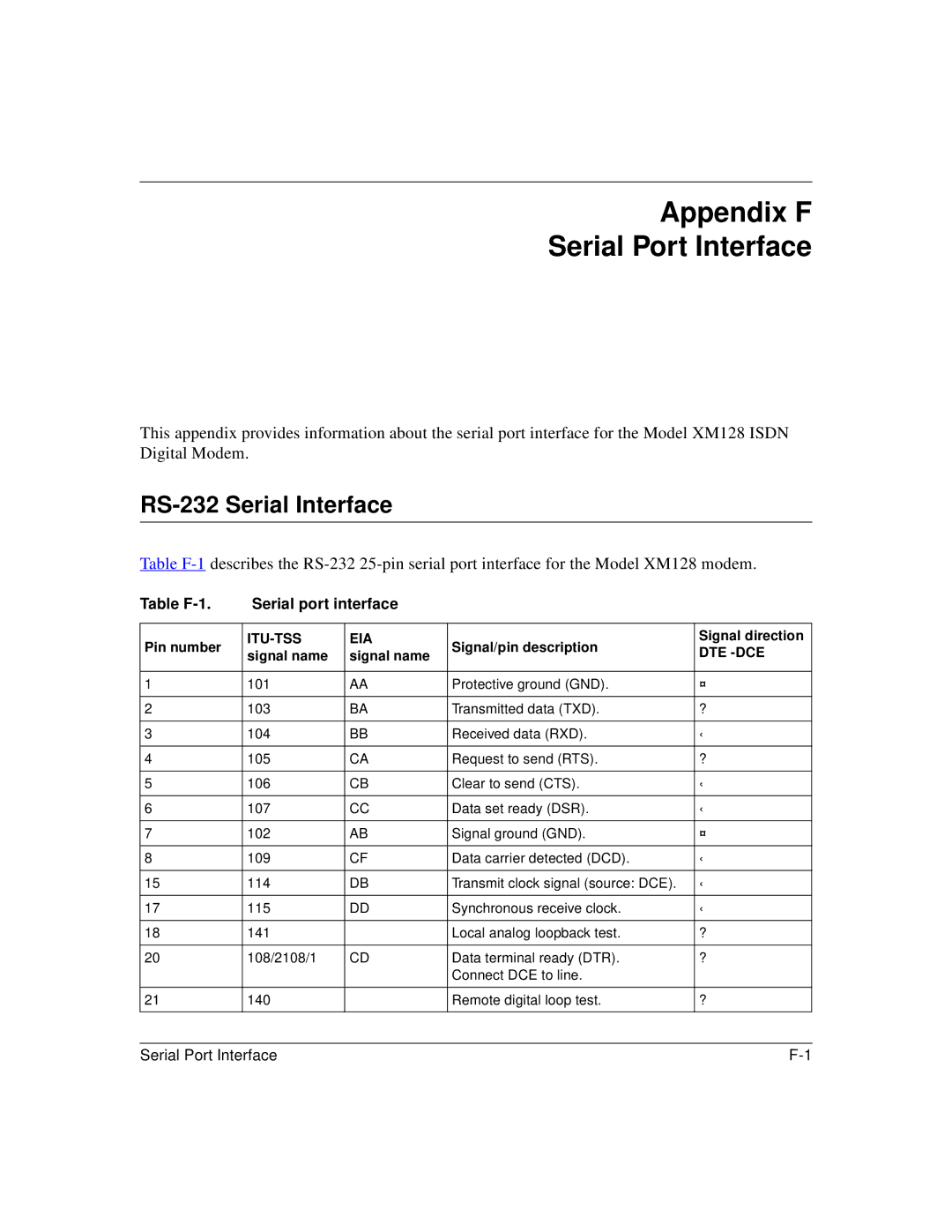
This appendix provides information about the serial port interface for the Model XM128 ISDN Digital Modem.
RS-232 Serial Interface
Table
Table | Serial port interface |
|
| ||
|
|
|
|
| |
Pin number | EIA | Signal/pin description | Signal direction | ||
signal name | signal name | DTE | |||
|
| ||||
|
|
|
|
| |
1 | 101 | AA | Protective ground (GND). | ¤ | |
|
|
|
|
| |
2 | 103 | BA | Transmitted data (TXD). | ? | |
|
|
|
|
| |
3 | 104 | BB | Received data (RXD). | ‹ | |
|
|
|
|
| |
4 | 105 | CA | Request to send (RTS). | ? | |
|
|
|
|
| |
5 | 106 | CB | Clear to send (CTS). | ‹ | |
|
|
|
|
| |
6 | 107 | CC | Data set ready (DSR). | ‹ | |
|
|
|
|
| |
7 | 102 | AB | Signal ground (GND). | ¤ | |
|
|
|
|
| |
8 | 109 | CF | Data carrier detected (DCD). | ‹ | |
|
|
|
|
| |
15 | 114 | DB | Transmit clock signal (source: DCE). | ‹ | |
|
|
|
|
| |
17 | 115 | DD | Synchronous receive clock. | ‹ | |
|
|
|
|
| |
18 | 141 |
| Local analog loopback test. | ? | |
|
|
|
|
| |
20 | 108/2108/1 | CD | Data terminal ready (DTR). | ? | |
|
|
| Connect DCE to line. |
| |
|
|
|
|
| |
21 | 140 |
| Remote digital loop test. | ? | |
|
|
|
|
| |
|
|
|
|
| |
Serial Port Interface |
|
| |||