|
|
| Reference Guide for the Model XM128 ISDN Digital Modem | |
|
|
|
|
|
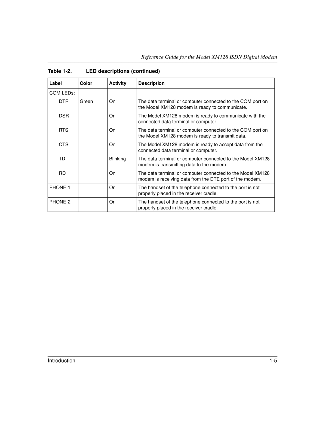
Table | LED descriptions (continued) | |||
|
|
|
|
|
Label | Color | Activity | Description |
|
|
|
|
|
|
COM LEDs: |
|
|
|
|
DTR | Green | On | The data terminal or computer connected to the COM port on |
|
|
|
| the Model XM128 modem is ready to communicate. |
|
DSR |
| On | The Model XM128 modem is ready to communicate with the |
|
|
|
| connected data terminal or computer. |
|
RTS |
| On | The data terminal or computer connected to the COM port on |
|
|
|
| the Model XM128 modem is ready to transmit data. |
|
CTS |
| On | The Model XM128 modem is ready to accept data from the |
|
|
|
| connected data terminal or computer. |
|
TD |
| Blinking | The data terminal or computer connected to the Model XM128 |
|
|
|
| modem is transmitting data to the modem. |
|
RD |
| On | The data terminal or computer connected to the Model XM128 |
|
|
|
| modem is receiving data from the DTE port of the modem. |
|
|
|
|
|
|
PHONE 1 |
| On | The handset of the telephone connected to the port is not |
|
|
|
| properly placed in the receiver cradle. |
|
|
|
|
|
|
PHONE 2 |
| On | The handset of the telephone connected to the port is not |
|
|
|
| properly placed in the receiver cradle. |
|
|
|
|
|
|
Introduction |