SpecificationChapter 10:
Jumper and Potentiometer
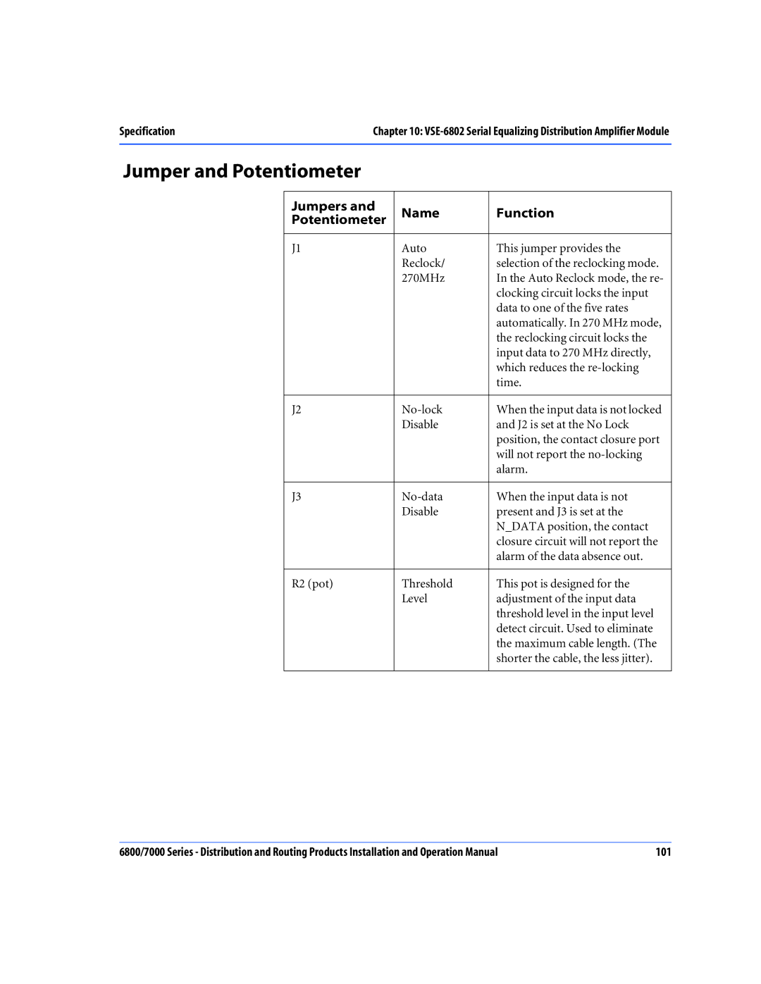
Jumpers and | Name | Function |
Potentiometer | ||
|
|
|
J1 | Auto | This jumper provides the |
| Reclock/ | selection of the reclocking mode. |
| 270MHz | In the Auto Reclock mode, the re- |
|
| clocking circuit locks the input |
|
| data to one of the five rates |
|
| automatically. In 270 MHz mode, |
|
| the reclocking circuit locks the |
|
| input data to 270 MHz directly, |
|
| which reduces the |
|
| time. |
|
|
|
J2 | When the input data is not locked | |
| Disable | and J2 is set at the No Lock |
|
| position, the contact closure port |
|
| will not report the |
|
| alarm. |
|
|
|
J3 | When the input data is not | |
| Disable | present and J3 is set at the |
|
| N_DATA position, the contact |
|
| closure circuit will not report the |
|
| alarm of the data absence out. |
|
|
|
R2 (pot) | Threshold | This pot is designed for the |
| Level | adjustment of the input data |
|
| threshold level in the input level |
|
| detect circuit. Used to eliminate |
|
| the maximum cable length. (The |
|
| shorter the cable, the less jitter). |
|
|
|
6800/7000 Series - Distribution and Routing Products Installation and Operation Manual | 101 |