Chapter 14:
Test Points
|
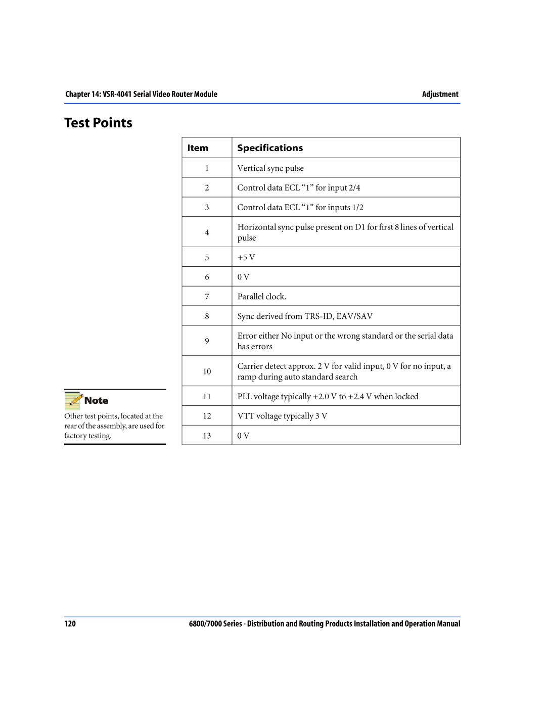
| Item | Specifications | |
|
|
|
| |
|
| 1 | Vertical sync pulse | |
|
|
|
| |
|
| 2 | Control data ECL “1” for input 2/4 | |
|
|
|
| |
|
| 3 | Control data ECL “1” for inputs 1/2 | |
|
|
|
| |
|
| 4 | Horizontal sync pulse present on D1 for first 8 lines of vertical | |
|
| pulse | ||
|
|
| ||
|
|
|
| |
|
| 5 | +5 V | |
|
|
|
| |
|
| 6 | 0 V | |
|
|
|
| |
|
| 7 | Parallel clock. | |
|
|
|
| |
|
| 8 | Sync derived from | |
|
|
|
| |
|
| 9 | Error either No input or the wrong standard or the serial data | |
|
| has errors | ||
|
|
| ||
|
|
|
| |
|
| 10 | Carrier detect approx. 2 V for valid input, 0 V for no input, a | |
|
| ramp during auto standard search | ||
|
|
| ||
|
|
|
| |
|
| 11 | PLL voltage typically +2.0 V to +2.4 V when locked | |
|
|
|
| |
Other test points, located at the | 12 | VTT voltage typically 3 V | ||
rear of the assembly, are used for |
|
| ||
13 | 0 V | |||
factory testing. | ||||
|
|
|
| |
120 | 6800/7000 Series - Distribution and Routing Products Installation and Operation Manual |
