C33975.85--B0
DNT2Mi sp/mp
Product code Product versions
Contents
Maintaining DNT2Mi
Appendix a
Issue 2-0 en
Document Date Comment
Summary of changes
Issue 2-0 en
About this document
Issue 2-0 en
Introduction to DNT2Mi
704/2M EIA-530-A Ethernet D2048
DNT2Mi Multiport Single-port
Network
Local
Data Exchange
DNT2Mi multiport
Data
Front panel
Construction and interfaces
Local management interface
Indicators and keys
Tx a OUT
107
Tx b OUT
108 109
DNT2Mi NMS/10
DNT2Mi
704 Two upper Adapters are Upside down
Rear panel
Pin modular jack, RJ-11 Line 123456
Terminal interfaces
703/2M BNC
704/2M
EIA-530-A D2048
703/64k 703/2M
DTE interface adapter units
Ethernet
Grounding of DNT2Mi
Electromagnetic compatibility
Do not cover Approx 100 mm Approx mm
Clearances around DNT2Mi
Inserting DTE interface units
Work order
Inserting DTE interface units into DNT2Mi single-port
Screws
Installing DNT2Mi on a wall
Free-standing installation
Installing DNT2Mi on a wall or into a rack
To install DNT2Mi on a wall
Mm bit 45 mm
Marking of fixing points for wall screws
Installing a modem shelf into a 19-inch rack
Uninstalling a wall-mounted DNT2Mi
Rack screws M6x16 Rack nuts Inch rack Allen-head
Installing DNT2Mi in a modem shelf
To install DNT2Mi in a modem shelf
Uninstalling DNT2Mi from a modem shelf
Uninstalling DNT2Mi from a modem shelf
Mains Voltage
Connecting power supply
Earthing bar Fuse 2 a Max a + bar 48V system
Principle of a positive-grounded DC power system
Remote power feed connection
Grounding principle of the remote-powered system
Strain relief
Troubleshooting
Recommended actions after the installation
Completing the installation
Verifying the installation
Adjusting the LCD display
Commissioning DNT2Mi
Automatic power-up test
Management
Timing source
Line settings
Port settings
Protection settings
Time slot settings Q1 6,5
Monitoring a line
Measurements
Global parameters
Default values
Explanation of noise margin
Port parameters, V-series V.11, V.28, V.35 or EIA-530-A
Line parameters
Multiplexer parameters
Port parameters, G.704/2M
Port parameters
Port parameters, G.703/64k
Factory values
Factory values
Issue 2-0 en
Example of general information
Getting general information
DNT2Mi AS Line No incoming signal
Monitoring alarms
Alarms
Testing
Tests available for DNT2Mi
Following tests are available for testing a DNT2Mi terminal
Network test loop all ports
Local test loop in a port
Remotely controlled network test loop
Checking measurements and statistics
Information Abbreviation and/or Description Ratio
Statistics values via Q1
Using front panel menus
LED Indicators
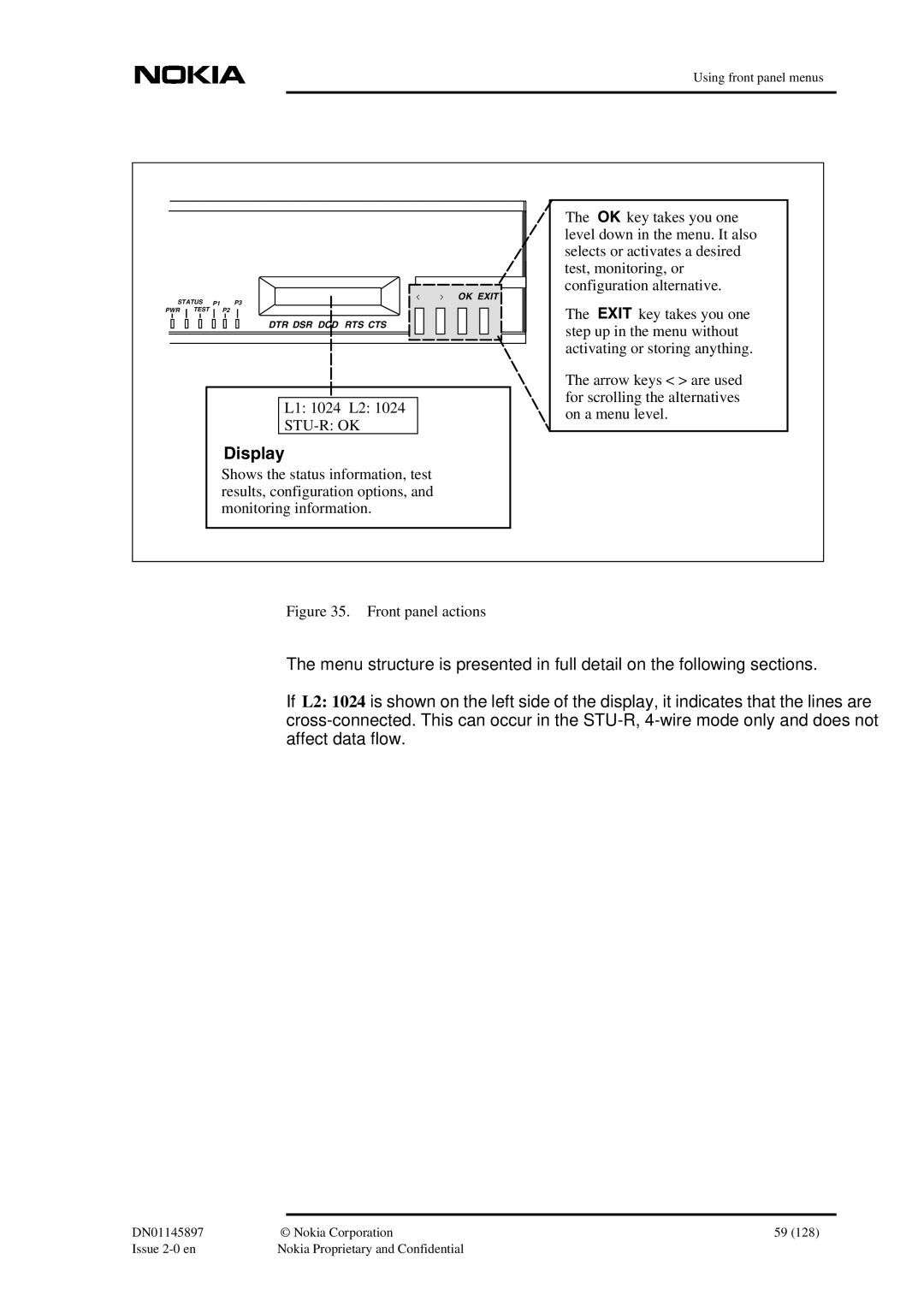
Front panel actions
L1 1024 L2
Main menu levels
Configuring DNT2Mi
Using front panel menus
Configuring port 1 / V.xx type interfaces
Configuring a port
Configuring port 2 and port 3 / V.xx type interfaces
Configuring ports / X.21 interfaces
Configuring ports / G.703/64k interfaces
Configuring ports / G.704 interfaces
Configuring ports / VF interfaces
Front panel menus for line settings
Configuring a line
Front panel menus for common settings
Configuring common settings
Front panel menus for default settings
Default settings
Testing a line
Testing DNT2Mi
Testing a port
Front panel menus for testing the equipment
Testing the equipment
Monitoring a port
Monitoring DNT2Mi
Front panel menus for monitoring a line
Monitoring a line
Front panel menus for monitoring alarms
Monitoring alarms
Self test results
Self testing
Monitoring equipment information
General
Using Q1 menus
User privileges
Fault display
Identifications Controls Settings Measurements Statistics
DNT settings
2,1
2,0
4,1,2
4,0
4,1
4,1,1
Port #
Controls menu
Settings menu structure
3,2,3
3,1
3,2
3,1,4
3,1,2
Using Q1 menus Power backoff Display
1...9
Port#
1,TS#
Port#,6
Port#,2
Port#,4
Port#,5
Port #,3,5
704/2M & D2048 Interface settings 6,4, port #
Port#,3 Only with D2048 adapter Port #,3,1
Port #,3,4
Port #,3,3,2
Type inteface settings Port#,3
Port #,3,2
Port #,3,3
Port#,3 Port#,3,1
Interface settings Port#,3
Port #,3,4 VF Interface settings Port#,3
703/2M Interface settings Port #
703/64k Interface settings Port #
DNT measurements
Measurements menu structure
Port#,4,1 Port#,4,2
Port#,4,3
Port#,3,1 Port#,3,2
4,3
3,1/8,2,3,2
4,1/8,2,4,2
10,4,2
10,1
10,4
10,4,1
Display controls Type Control Port1 Port2 Port3 Line 704
DNT settings
DNT controls
Display 6,0
Service options 6,1
Timing source 6,2
114 115
114 Line Shdsl 115 Timing
113 114
115 Timing
Principle of the Line interface menu
Line settings 6,3
Using Q1 menus
Measured Shdsl symmetric PSD and mask 2-w, 2M
Function of the line power loss
No noise
9000 8000 7000 6000 5000 4000 3000 2000 1000
Port settings 6,4, port #
Type interface settings 6,4, port #,3
104 115
103 113 114 104 115
Line Shdsl Timing
103 114
103 114 104 115
103
114 104 115
Line Shdsl TimingTiming
CTS use 6,4, port #,3,3,1
From the Port Menu, select As in line
From the Port Menu, select 1st TS TS1
From the Port Menu, select 1st TS TS1 Special
703/64k-type interface settings 6,4, port #,3
Time slot use 6,5
Default settings 6,6
Factory settings 6,7
Port/Line statistics submenu
Statistics
User privileges
DNT2Mi single-port dimensions
Dimensions
DNT2Mi multiport dimensions
DNT2Mi power supply
Power supply
Unit identification
Line interfaces
Environmental and mechanical requirements
Ambient conditions
Environmental and mechanical requirements
DNT2Mi climatogram Mean time between failure Mtbf
Electromagnetic compatibility
EMC requirements
Safety and protection
DNT2Mi safety and protection
Port settings
Appendix a Commissioning chart
General settings
Line measurements
BER test results
Line Port
Statistics
Issue 2-0 en
EMC
Glossary Abbreviations
ESR
PWR
Dynanet
Terms