Installation Modules
Ices statement Canada only
Statement of conditions
International regulatory statements of conformity
Vcci statement Japan/Nippon only
CE marking statement Europe only
EN 55 022 statements
EN 55 024 statement
EN 60 950 statement
Bsmi statement for 8010, 8006 and 8003 chassis Taiwan only
NOM statement 8010, 8006, and 8003 chassis Mexico only
Información NOM unicamente para México
Nortel Networks Inc. software license agreement
General
Page
Contents
Copyright 2005-2007, Nortel Networks
Installing the jumper on an ESM 139
Contents
Document changes
Features
Other changes
New in this release
Navigation
Prerequisites
Introduction
Metro Ethernet Routing Switch 8600 modules
Metro Ethernet Routing Switch 8600 modules
Copyright 2005-2007, Nortel Networks
DS-3 MDA
8003 8006 8010 Module type Port type 8010co
8683POSM OC-3c MDA See Note OC-12c MDA
Metro Ethernet Routing Switch 8600 R module feature set
Metro Ethernet Routing Switch 8600 modules
Mode configuration requirements
QoS and Traffic Filters NN46220-508
8608GBE/8608GBM module
ESM 8668 Metro Ethernet Services Module
8608GBE and 8608GBM modules
8608GBE/8608GBM module LEDs Type Label Color/State Meaning
Gbic order number Gbic type
8608GBE/8608GBM module LEDs
Type Label Color/State Meaning
8608GTE and 8608GTM modules
8608GTE/8608GTM module LEDs Type Label Color/State Meaning
8608GTE/8608GTM module
8608GTE/8608GTM module LEDs
Type Label Color/State Meaning
8608SXE module LEDs
8608SXE module
8608SXE module
8608SXE module LEDs Type Label Color/State Meaning
8616GTE module
8616GTE module
8616GTE module LEDs
8616GTE module LEDs Type Label Color/State Meaning
8616SXE module
8616SXE module LEDs Type Label Color/State Meaning
8616SXE module
8616SXE module LEDs
8624FXE module
8624FXE module LEDs Type Label Color/State Meaning
8624FXE module
8624FXE module LEDs
8630GBR module
8630GBR qualified SFP transceivers SFP order number SFP type
8630GBR module
8630GBR module LEDs Type Label Color/State Meaning
8630GBR module LEDs
M mode configuration requirements
8632TXE/8632TXM module
8632TXE and 8632TXM modules
8632TXE/8632TXM module LEDs Type Label Color/State Meaning
8632TXE/8632TXM module LEDs
Gbic
8648GTR module LEDs
8648GTR module
8648GTR module
8648GTR module LEDs Type Label Color/State Meaning
8648TXE/8648TXM module
8648TXE and 8648TXM modules
8648TXE/8648TXM module LEDs Type Label Color/State Meaning
8648TXE/8648TXM module LEDs
Type Label Color/State Meaning
Metro ESM 8668 LEDs Label Color/State Meaning
Metro ESM
8672ATME/8672ATMM module with an OC-12c/STM-4 MDA
8672ATME and 8672ATMM modules
Label Color/State Meaning
8672ATME/8672ATMM module LED Color/State Meaning
8681XLR module
8681XLR module
8681XLR module LEDs Type Label Color/State Meaning
8681XLR module LEDs
8681XLW module
8681XLW module
8681XLW module LEDs Type Label Color/State Meaning
8681XLW module LEDs
8683POSM module with an OC-12c/STM-4 MDA
8683POSM module
8683POSM module LED Color/State Meaning
8683XLR module
8683XLR module
8683XLR qualified XFP transceivers XFP order number XFP type
AA1403005 10GBaseSR AA1403001 10GBaseLR
XFP order number XFP type
Both Blinking Port is disabled Green
AA1403003 10GBaseER AA1403006 10GBaseZR
8683XLR module LEDs
Type Label Color/State Meaning
8683XZR qualified XFPs XFP order number XFP type
8683XZR module
8683XZR module
8683XZR Module LEDs Type Label Color/State Meaning
8683XZR Module LEDs
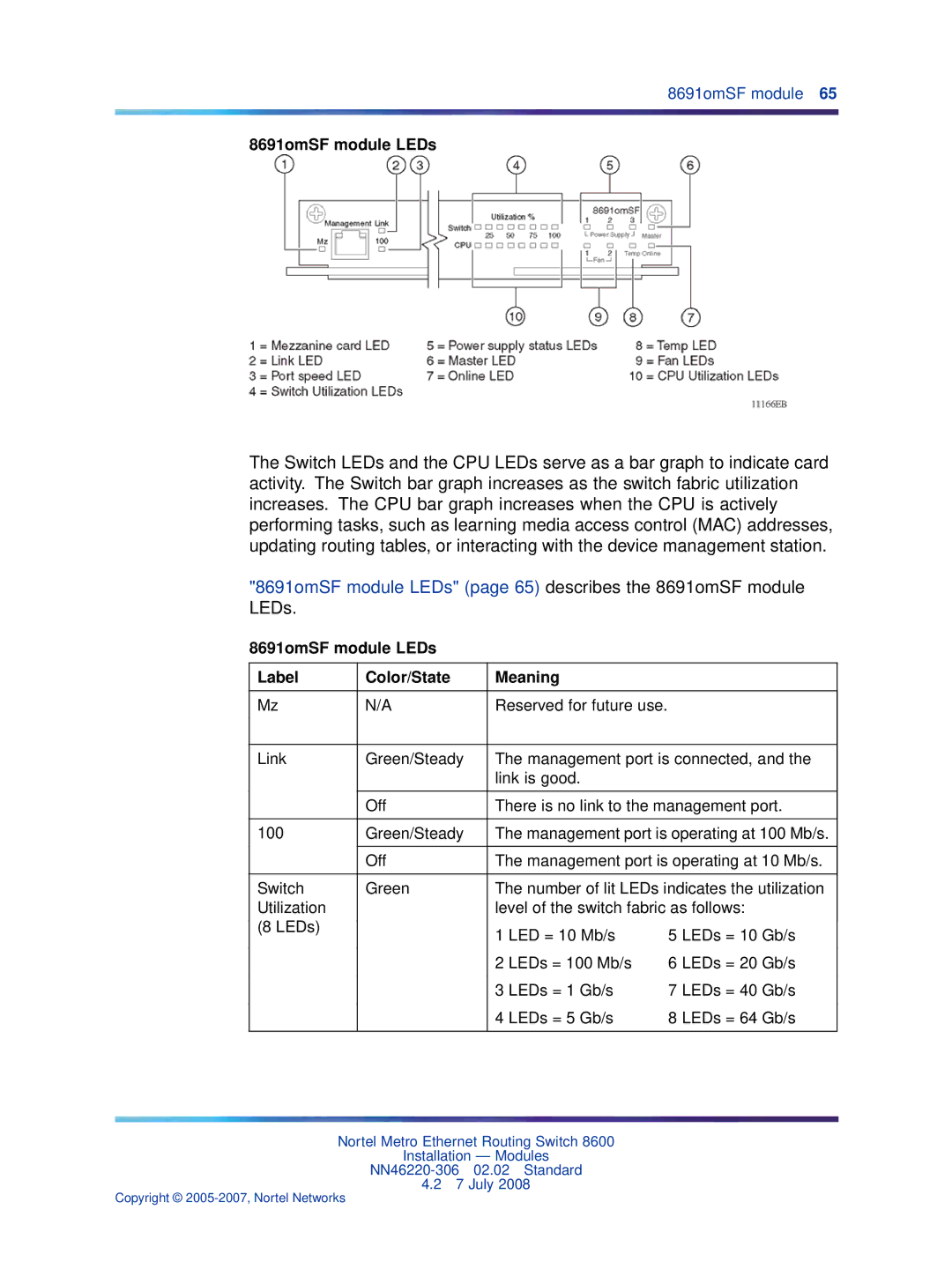
8691omSF module
8691omSF module
Metro Ethernet Routing Switch 8600 modules
8691omSF module LEDs Label Color/State Meaning
8691omSF module LEDs
CPU
Ethernet management port
Reset button
DCE/DTE switch
8692omSF module
Serial ports
8692omSF module
8692omSF module LEDs
LEDs
8692omSF module LEDs Label Color/State Meaning
Ethernet management port
Reset button
Removing a filler panel
Step Action
Procedure steps
Prerequisites
Installing a filler panel
Installing and replacing a module
Removing a module
Navigation
Conf slot slotnum state disable
Loosening screws on the module 8003, 8006, and 8010 chassis
Loosening screws on the module 8010co chassis
Removing a module 8003, 8006, and 8010 chassis
Ejecting the module from the chassis 8010co chassis
Removing a module 8010co chassis
Installing a module
Electrostatic discharge can damage hardware
Installing a module 8003, 8006, and 8010 chassis
Installing a module 8010co chassis
Seating the backplane connectors 8010co chassis
Conf slot slotnum state enable
Connecting a modem to the switch
Connecting a PC or terminal to the switch
Procedure job aid PC and terminal settings
PC and terminal settings Parameter Value
Modem settings Setting Value
Procedure job aid Modem settings
Data set ready DSR signal Ready to send RTS signal Ignored
Disconnect
Setting Value
Connecting a network management station to the switch
UTP/STP
See Note None Ethernet ports
550 m @
Ohm coaxial None 450 ft DS-3 or Cable 137 m
125 µm None OC-3 or Single-mode 15 km
Fiber-optic cable OC-3
125 µm None OC-3 Single-mode 15 km Fiber-optic cable
8683POSM OC-3
Procedure steps
Managing cables 8010co chassis
Managing cables 8010, 8006, 8003 chassis
Image filenames for 8672ATME/8672ATMM/8683POSM Module
Initializing the 8672ATME, 8672ATMM, and 8683POSM modules
8672ATME 8672ATMM 8683POSM
Image filename
Initializing the 8672ATME and 8672ATMM modules
ATM card in slot number is online
Unsuccessful download screen output
Initializing the 8683POSM module
POS card in slot number is online
101
General specifications
Environmental specifications
Standards supported
Data rate and encoding
Address database
Performance specifications 64-byte packets
Electromagnetic emissions
Safety agency approvals
Electrical specifications
Physical specifications
Connector type
GBICs
See Note 1000BaseSX 62.5 200 850
1000BaseSX 62.5 160 850
See Note 1000BaseSX 400 To-4 850
1000BaseSX 500 To-4 850
Height .8 cm
Cable specifications
1000BaseT Gbic
Port connectors
Bidirectional Data D + BIDD+
Connector Pin number Signal
Bidirectional Data D Bidd
197 887 hr
Optical specifications
147 602 hr
Height .8 cm Width 15.4 in .1 cm Depth 18.5 in .0 cm Weight
178 403 hr
Input power Maximum Thermal rating 396 Btu/hr maximum
Wavelength 1300 nm Optical budget
Input power Maximum Thermal rating 193 Btu/hr maximum
320 972 hr
Gigabit Ethernet SFP transceivers
Input power Maximum Thermal rating 614 Btu/hr maximum
177 525 hr
Height 13.4 mm Width
Multimode fiber optic LC or MT-RJ
Depth 22 in 54.4 mm Weight Varies with transceiver type
Single-mode fiber optic LC
217 744 hr
1000BaseT transceiver
Input power
Type Category 5 copper unshielded twisted pair
Maximum distance 328 ft 100m
Height .8 cm Width
Maximum Thermal rating 614 Btu/hr maximum
190 803 hr
Input power Maximum Thermal rating 261 Btu/hr maximum
15.4 in .1 cm Depth 18.5 in .0 cm Weight Lb 3.6 kg
244 708 hr
Input receive data + RX+
Connector types
Input power 100 W Thermal rating 0 50 C
162 000 hr
Pluggable Small Form Factor Optics SFP modules
OC-3c MDA MT-RJ OC-12c MDA Duplex SC
222 103 hr
8681XLR module
Compatible with STM-64 Module Performance 64 byte packets
Yes
Compatible with STM-64
10GBaseLW 1310nm serial PMD
255 693 hr
10.3125 Gb/s with 64b/66b encoding
184 230 hr
LC Duplex
XFPs
Dependent on GBIC, XFP, or SFP
10.3125 Gb/s LAN or 9.953 Gb/s WAN with 64b/66b encoding
Port type 10GBaseR/W
Management port
Modem serial port
Console serial port
TXD Output RXD Input DSR Input DTR Output
DTR Output DSR Input CTS Input RTS Output
Input power Maximum Thermal rating 241 Btu/hr maximum
Pin assignments DTE to DCE Switch Modem Signal Pin number
DCE DB-25
355 643 hr
Pin assignments 8692omSF module Connector Pin number Signal
Modem serial port
Copyright 2005-2007, Nortel Networks
135
Procedure steps
Aligning the CPU daughter card connectors
CPU daughter card installation kit
Copyright 2005-2007, Nortel Networks
Securing the daughter card to the 8692 Series CPU
Installing the jumper on an ESM
ESM 8668, P1 connector header
P1 connector header with jumper installed
P1 connector header, pins 5
Conf slot slot-number state en
Index
Description 37, 37
Index
Index
Index
Index
Page
Installation Modules