RTU-292 Operations Manual
6.5.3 VOX SENSITIVITY MEASUREMENT
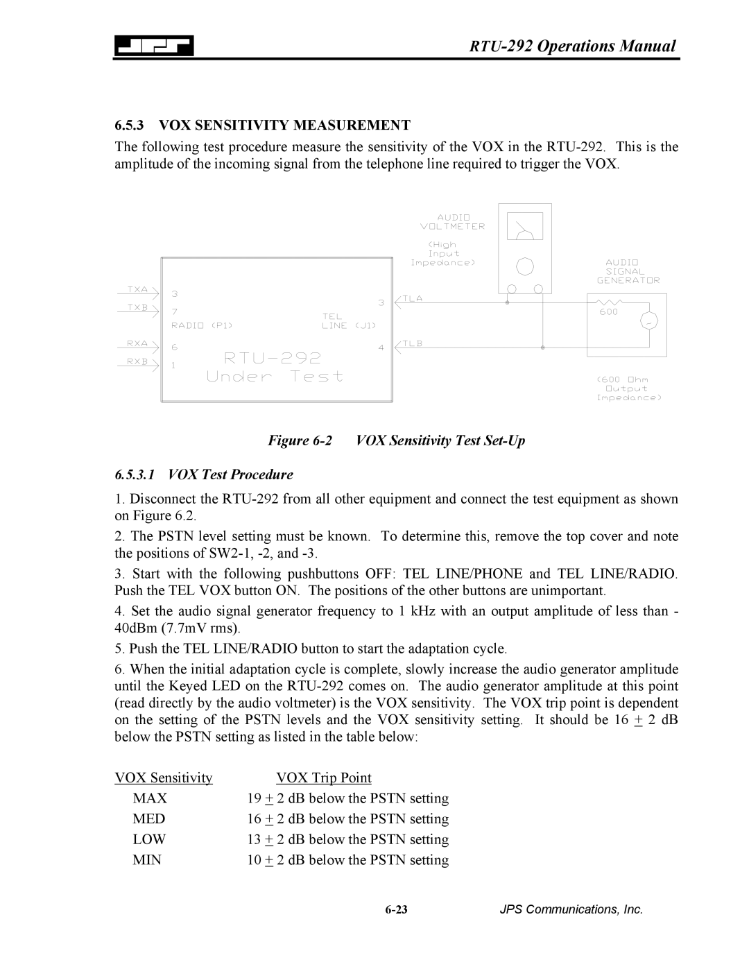
The following test procedure measure the sensitivity of the VOX in the
Figure 6-2 VOX Sensitivity Test Set-Up
6.5.3.1 VOX Test Procedure
1.Disconnect the
2.The PSTN level setting must be known. To determine this, remove the top cover and note the positions of
3.Start with the following pushbuttons OFF: TEL LINE/PHONE and TEL LINE/RADIO. Push the TEL VOX button ON. The positions of the other buttons are unimportant.
4.Set the audio signal generator frequency to 1 kHz with an output amplitude of less than - 40dBm (7.7mV rms).
5.Push the TEL LINE/RADIO button to start the adaptation cycle.
6.When the initial adaptation cycle is complete, slowly increase the audio generator amplitude until the Keyed LED on the
VOX Sensitivity | VOX Trip Point |
|
MAX | 19 + 2 dB below the PSTN setting |
|
MED | 16 + 2 dB below the PSTN setting |
|
LOW | 13 + 2 dB below the PSTN setting |
|
MIN | 10 + 2 dB below the PSTN setting |
|
| JPS Communications, Inc. |