2.8 D/A Conversion
The
zD/A output register, BASE+4/BASE+5/BASE+6/BASE+7, (sec. 2.4.3)
zJP1 jumper set to internal reference voltage
zJP2 jumper set to internal or external reference voltage (sec. 2.3.2)
zIf JP2 is set to internal and JP1 is set to
zIf JP2 is set to internal and JP1 is set to
zIf JP2 is set to external, the external reference voltage can be AC/DC +/- 10V
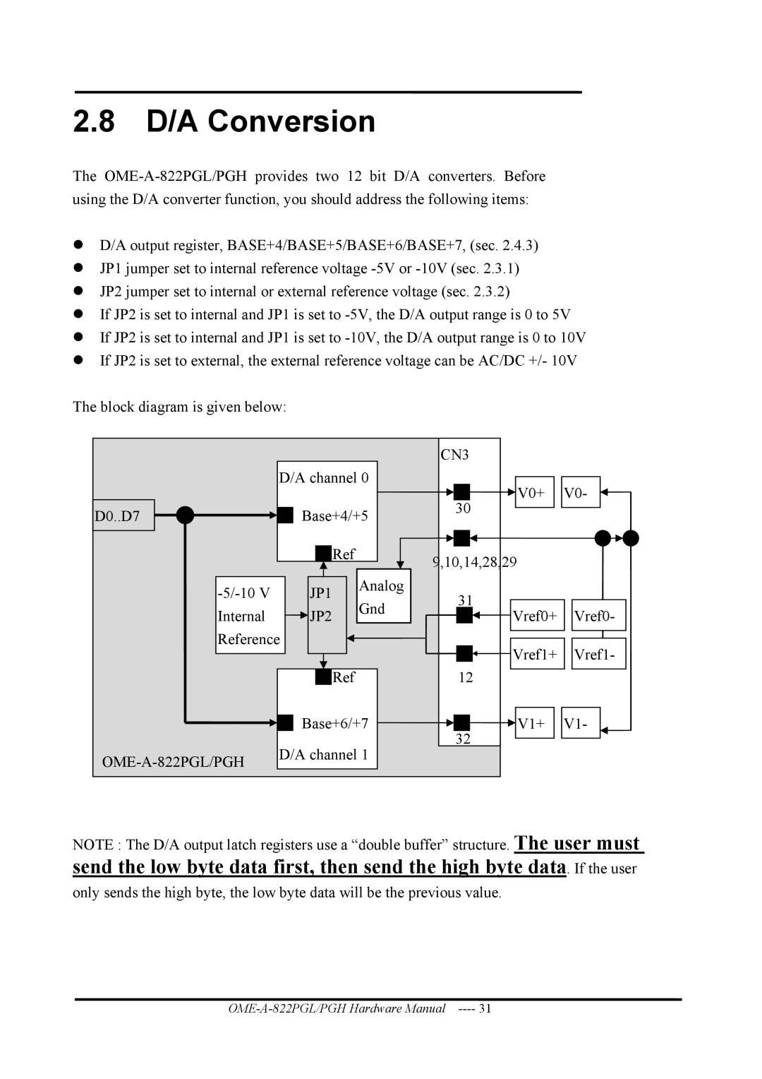
The block diagram is given below:
|
|
| CN3 |
| |
| D/A channel 0 | V0+ | V0- | ||
|
|
| |||
D0..D7 | Base+4/+5 | 30 |
| ||
|
| ||||
|
| Ref | 9,10,14,28,29 |
| |
|
|
|
| ||
JP1 | Analog | 31 |
| ||
Gnd |
| ||||
|
|
| |||
Internal | JP2 | Vref0+ | Vref0- | ||
| |||||
Reference |
| Vref1+ | Vref1- | ||
|
|
| |||
|
| Ref | 12 |
| |
| Base+6/+7 | V1+ | V1- | ||
| D/A channel 1 | 32 |
| ||
|
| ||||
|
|
|
| ||
NOTE : The D/A output latch registers use a “double buffer” structure. The user must
send the low byte data first, then send the high byte data. If the user
only sends the high byte, the low byte data will be the previous value.