2 | Parts of the Pump Motor |
| |
|
|
2.1 Front View
|
| 2 |
| |
| RPM | TIME | 3 | |
|
| |||
INLET | FLOW | TOTAL | PRIME | |
SELECT | RATE | VOLUME | ||
| ||||
TEMP | TUBE ID | CALIBRATE | START | |
STOP | ||||
|
|
| ||
1 |
|
|
| |
|
| 4 |
|
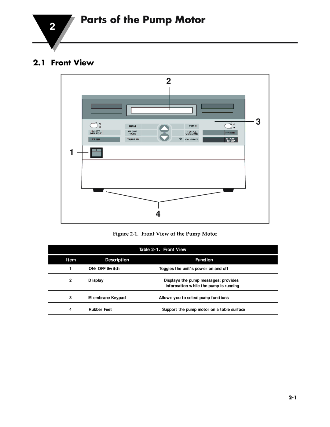
Figure 2-1. Front View of the Pump Motor
|
| Table |
|
|
|
Item | Description | Function |
1 | ON/OFF Switch | Toggles the unit’s power on and off |
|
|
|
2 | Display | Displays the pump messages; provides |
|
| information while the pump is running |
|
|
|
3 | Membrane Keypad | Allows you to select pump functions |
|
|
|
4 | Rubber Feet | Support the pump motor on a table surface |
|
|
|
