6 | Operating the Pump Motor in the | |
RUNNING Display Mode | ||
| ||
|
|
6.1 The RPM Mode
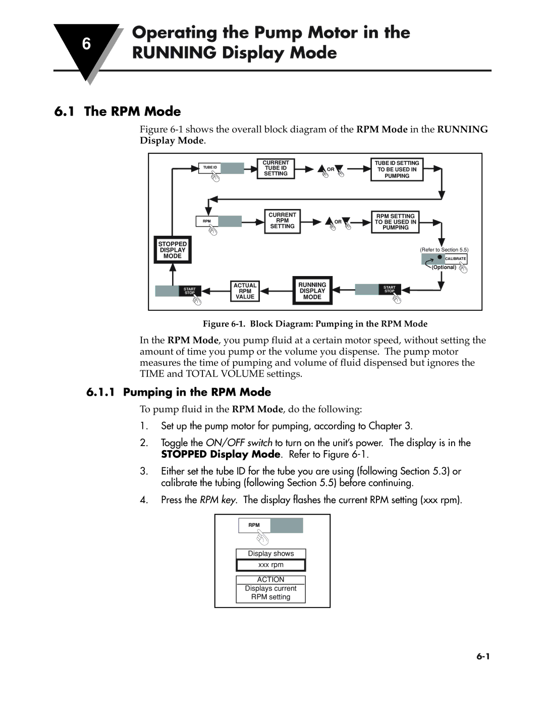
Figure 6-1 shows the overall block diagram of the RPM Mode in the RUNNING Display Mode.
STOPPED |
DISPLAY |
MODE |
START
STOP
| CURRENT | OR | TUBE ID SETTING |
TUBE ID | TUBE ID | TO BE USED IN | |
| SETTING |
| PUMPING |
|
|
|
| CURRENT |
| RPM SETTING |
RPM | RPM | OR | TO BE USED IN |
| SETTING |
| PUMPING |
(Refer to Section 5.5)
CALIBRATE
(Optional) ![]()
ACTUAL | RUNNING | START |
RPM | DISPLAY | STOP |
VALUE | MODE |
|
Figure 6-1. Block Diagram: Pumping in the RPM Mode
In the RPM Mode, you pump fluid at a certain motor speed, without setting the amount of time you pump or the volume you dispense. The pump motor measures the time of pumping and volume of fluid dispensed but ignores the TIME and TOTAL VOLUME settings.
6.1.1 Pumping in the RPM Mode
To pump fluid in the RPM Mode, do the following:
1.Set up the pump motor for pumping, according to Chapter 3.
2.Toggle the ON/OFF switch to turn on the unit’s power. The display is in the STOPPED Display Mode. Refer to Figure
3.Either set the tube ID for the tube you are using (following Section 5.3) or calibrate the tubing (following Section 5.5) before continuing.
4.Press the RPM key. The display flashes the current RPM setting (xxx rpm).
RPM
Display shows
xxx rpm
ACTION
Displays current
RPM setting
