2Parts of the Pump Motor
2.2 Left Side View
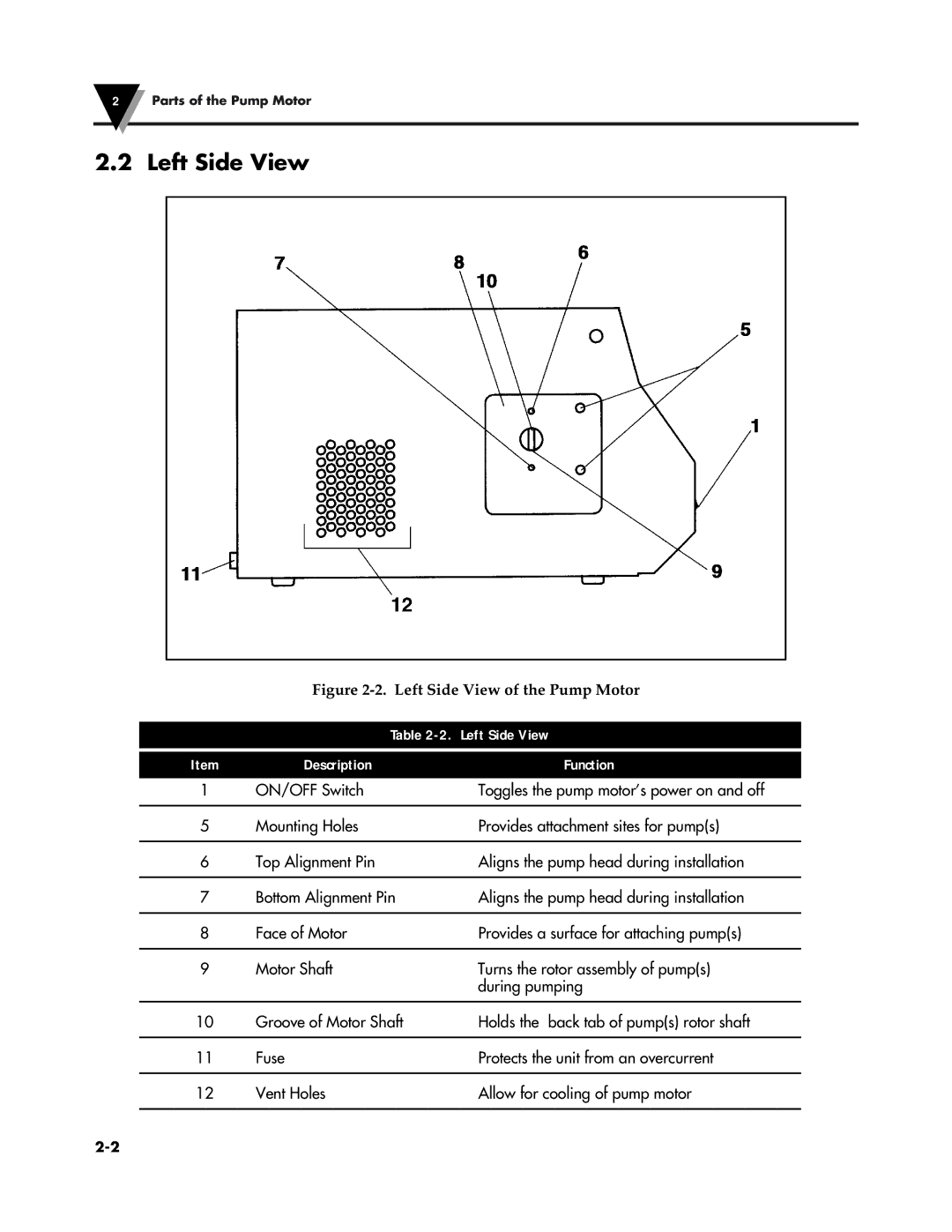
Figure 2-2. Left Side View of the Pump Motor
| Table | |
|
|
|
Item | Description | Function |
1 | ON/OFF Switch | Toggles the pump motor’s power on and off |
|
|
|
5 | Mounting Holes | Provides attachment sites for pump(s) |
|
|
|
6 | Top Alignment Pin | Aligns the pump head during installation |
|
|
|
7 | Bottom Alignment Pin | Aligns the pump head during installation |
|
|
|
8 | Face of Motor | Provides a surface for attaching pump(s) |
|
|
|
9 | Motor Shaft | Turns the rotor assembly of pump(s) |
|
| during pumping |
|
|
|
10 | Groove of Motor Shaft | Holds the back tab of pump(s) rotor shaft |
|
|
|
11 | Fuse | Protects the unit from an overcurrent |
|
|
|
12 | Vent Holes | Allow for cooling of pump motor |
|
|
|
