3Getting Started

3.1.2 Attaching a Single Pump Directly to the Motor

CAUTION

Perform ALL of the steps in Chapter 3 before turning the motor on.

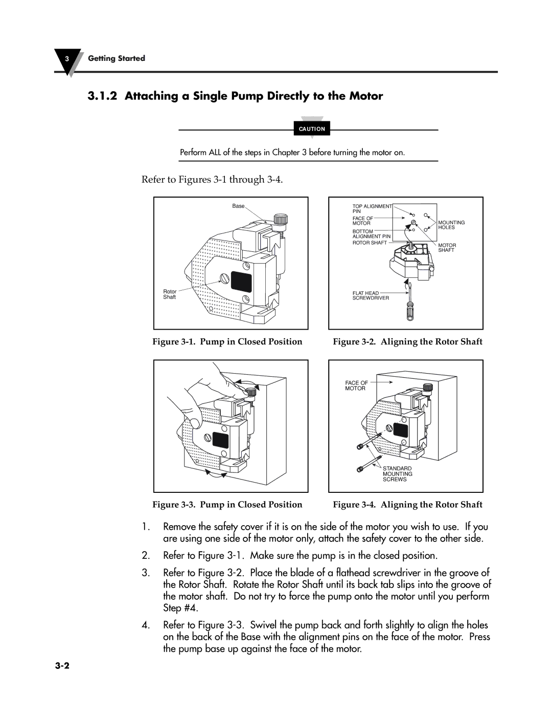
Refer to Figures 3-1 through 3-4.

Base

Rotor

Shaft

TOP ALIGNMENT

PIN

FACE OF

MOTORMOUNTING HOLES

BOTTOM ALIGNMENT PIN

ROTOR SHAFT

MOTOR


SHAFT

FLAT HEAD

SCREWDRIVER

Figure 3-1. Pump in Closed Position

Figure 3-2. Aligning the Rotor Shaft

FACE OF

MOTOR

STANDARD

MOUNTING

SCREWS

Figure 3-3. Pump in Closed Position

Figure 3-4. Aligning the Rotor Shaft

1.Remove the safety cover if it is on the side of the motor you wish to use. If you are using one side of the motor only, attach the safety cover to the other side.

2.Refer to Figure 3-1. Make sure the pump is in the closed position.

3.Refer to Figure 3-2. Place the blade of a flathead screwdriver in the groove of the Rotor Shaft. Rotate the Rotor Shaft until its back tab slips into the groove of the motor shaft. Do not try to force the pump onto the motor until you perform Step #4.

4.Refer to Figure 3-3. Swivel the pump back and forth slightly to align the holes on the back of the Base with the alignment pins on the face of the motor. Press the pump base up against the face of the motor.

3-2

Page 21
Image 21
Omega Speaker Systems FPU5-MT-220, FPU5-MT-110 Attaching a Single Pump Directly to the Motor, Refer to Figures 3-1 through