Serviceguide
Revision History
General information
DRS5 Users Guide /usr/local/bin/fd /TPH15spoolM program
Page
Chapter
System Utilities
Machine Maintenance Procedures
Troubleshooting
FRU Field Replaceable Unit List
Page
Chapter
Features
Page
Page
Features
Privacy Control
Graphics
Storage Subsystem
Optical Media Drive
Special Keys and Controls
Dimension and Weight
Power Adapter and Battery
Ports
Software
Warranty
Optional Items
Environment
Top View
Top View Icon Description
HDD
Closed Front View
Closed Front View Icon Description
Rear View
Left View
Hdmi
Right View
Right View Icon Description
Base View
Base View Icon Description
Touchpad Basics
Using the Keyboard
Keyboard Lock Keys Lock key Description
Key Description
Windows Keys
10. Windows Keys
Functions supported by Windows XP
Hotkeys
11. Keyboard Hotkeys
Keyboard Hotkeys
System Block Diagram
10. System Block Diagram
Specification Tables
Computer specifications Metric Imperial
VGA
System Board Major Chips Specification
Processor Specification
LAN
Cores Bus Mfg Cache Package Voltage
Processor Specifications
CPU
Threads
Memory Combinations Slot 1 MB Slot 2 MB
System Memory Specification
Video Interface Specification
Bios
2MB
LAN Interface Specification
Keyboard Specification
Hard Disk Drive AVL components Specification
MK6465GSX MK7559GSXP
MK5065GSX WD6400BPVT-22HXZT1 WD7500BPVT-22HXZT1
Super-Multi Drive Specification
Applicable disc format
CPT/ CLAA156WB11A
LED Specification
LG/LP156WH2-TLEA
LCD Inverter not available with this model
Display Supported Resolution GPU Supported Resolution Bits
Display Supported Resolution LCD Supported Resolution Bits
Graphics Controller Specification
ATI
Camera Specification
Bluetooth Interface Specifications
Bluetooth Module Specifications
Audio Codec and Amplifier Specification
Mini Card Specification
3G Card not available in this model Specification
Audio Interface Specification
Wireless Module 802.11b/g/n Specification
Hdmi Port Specification
Battery Specification
USB Port Specification
Vram
Card Reader Specification
AC Adapter Specification
System Power Management Specification
QFN 48P
System LED Indicator Specification
System DMA Specification Legacy Mode Power Management
System Interrupt Specification Hardware IRQ System Function
CMOS/RTC
C6F
System Utilities
DOS Flash Utility WinFlash Utility
Bios Setup Utility
Navigating the Bios Utility
TK11BZ
Bios Information Parameter Description
Information
Uuid
Bios Main Parameter Description Format/Option
Main
Bios Main Parameter Description Format/Option
Bios Security Parameter Description Option
Security
Setting a Password
Removing a Password
Setup Notice
Boot
10. Bios Boot
Exit
Exit Parameters Description
Bios Flash Utilities
12. Bios Boot
DOS Flash Utility
13. DOS Flash Process
WinFlash Utility
15. InsydeFlash
Remove HDD/BIOS Password Utilities
16. Password Error Status
19. Unlock Password
Removing Bios Passwords
20. Cmos Jumper
Method
Cleaning Bios Passwords
23. Clean Bios Password
Using Boot Sequence Selector
Miscellaneous Tools
Using DMITools
Using the LAN MAC Eeprom Utility
25. LAN MAC Eeprom Parameter Description
Crisis Disk Recovery
27. USB Flash Crisis Disk
29. USB Flash Crisis Disk
System Utilities
Machine Maintenance Procedures
Page
Page
Page
Screw List
Introduction
Recommended Equipment
Maintenance Flowchart
ODD USB
Getting Started
AC Adapter Outlet
Battery Pack Removal
Battery Pack Installation
Dummy Card Installation
Dummy Card Removal
Keyboard Removal
Keyboard Latches
Keyboard Installation
ODD Optical Disk Drive Module Removal
ODD Module in Lower Cover
ODD Module Installation
Base Door Installation
Base Door Removal
Dimm Dual In-line Memory Module Module Removal
10. Component Location
Dimm Module Installation
M2.5*3.0
Wlan Wireless Local Area Network Board Removal
Wlan Board Installation
RTC Battery Removal
RTC Battery Installation
HDD Hard Disk Drive Module Removal
14. HDD Module
HDD Module Installation
Upper Cover Removal
16. Lower Cover Screw Location
18. Lower Cover Removal
Upper Cover Installation
Speaker Removal
20. Upper Cover Component Location
Speaker Installation
Power Board Removal
Power Board Installation
Touchpad Installation
Touchpad Removal
USB Board Removal
24. Component Location
USB Board Installation
M2.5*5.0
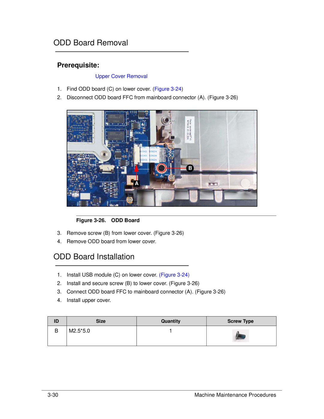
ODD Board Installation
ODD Board Removal
Bluetooth Board Removal
Bluetooth Board Installation
Mainboard Removal
28. Mainboard Location
29. Mainboard
Mainboard Installation
31. Mainboard
Fan Installation
Fan Removal
Heatsink Removal
33. Thermal Module
Heatsink Installation
35. Thermal Module
ICW50 CPU Thermal Screw
LCD Liquid Crystal Display Module Removal
36. LCD Hinge Screws
LCD Module Installation
DC-IN Cable Removal
38. DC-IN Cable Location
DC Cable Installation
LCD Bezel Removal
40. LCD Bezel
42. LCD Bezel
LCD Bezel Installation
M2.5*6.0
Camera Module Removal
44. Camera Module Location
Camera Module Installation
LCD Panel Removal
46. LCD Panel
LCD Panel Installation
M2.5*4.0
M2.0*3.0
LCD Bracket Installation
LCD Bracket Removal
Lvds Cable Removal
49. Lvds Cable
Lvds Cable Installation
Microphone Set Installation
Microphone Set Removal
Wlan Antenna Installation
Wlan Antenna Removal
Troubleshooting
Intermittent Problems Undetermined Problems Post Codes
Common Problems
Power On Issues
Power On Issue
No Display Issues
No Display Issue
Abnormal Video
LCD Failure
LCD Failure
Keyboard Failure
Keyboard Failure
Touchpad Failure
Touchpad Failure
Internal Speaker Failure
Internal Speaker Failure
Troubleshooting
Microphone Failure
Microphone Failure
USB Failure
USB Failure
Wireless Failure
Wireless Failure
Bluetooth Failure
10. Bluetooth Failure
Card Reader Failure
11. Card Reader Failure
Thermal Module Failure
12. Thermal Module Failure
Cosmetic Failure
13. Cosmetic Failure
Other Functions Failure
Intermittent Problems
Undetermined Problems
Post Code Range Phase
Post Codes
Peiswitchstack PEI
Peicpuhtreset PEI
Peimemoryinstall PEI
Peienterrecoverymode PEI
Dxesmmaccess DXE
Peirecoverystartflash PEI
DXECF9RESET
Dxesmarttimerinit DXE
Dxerelocatesmbase DXE
Bdsinstallhotkey BDS
Bdsbeforepciioinstall BDS
Dxefirstsmi DXE
Bdsentersetup BDS
Bdsenumerateallbootoption BDS
Bdsendofbootselection BDS
Bdsenterbootmanager BDS
S3SWITCHSTACK PEI
S3RESTOREMEMORYCONTROLLER PEI
S3INSTALLS3MEMORY PEI
S3BEFOREACPIBOOTSCRIPT PEI
10. InsydeH2ODDT Debugger Post Code Table
Troubleshooting
Jumper and Connector Locations
Page
Mainboard Jumper and Connector Locations
PJP1
PJP2
JHP1
JBT1
JP1
USB Board Jumper and Connector Locations
JUSB1 / JUSB2
Connect to mainboard w/ FFC
Power Board Jumper and Connector Locations
JP1
Clearing Password Check and Bios Recovery
Clearing Password Check
Bios Recovery by Crisis Disk
Clear Cmos Jumper
Steps for Bios Recovery from USB Storage
Jumper and Connector Locations
FRU Field Replaceable Unit List
Exploded Diagrams FRU List Screw List
FRU Field Replaceable Unit List
Exploded Diagrams
LCD Assembly Exploded Diagram
FRU List
Battery
FRU List
Adapter
Cable
CASE/COVER/BRACKET Assembly
DVD RW Drive
HDD/HARD Disk Drive
WD6400BPVT-22HXZT1, ML375M Sata 8MB
Sata 8MB LF F/W0001SDM1
BS,MK3265GSX Sata 8MB LF F/WGJ002J
Sata 8MB LF+HF F/WGN003J
Keyboard
FRU List
LCD
Glare W/ANTENNA*2, CCD 1.3M, RED PB Antenna WLAN-MAIN
LED COVER-RED PB
Glare W/ANTENNA*2, CCD 1.3M, Black GTW
LED COVER-BLACK GW
LCD Bezel for W/CMOS GW
Glare W/ANTENNA*2, CCD 1.3M, RED GTW Antenna WLAN-MAIN
LED COVER-RED GW
Mainboard
Heatsink
Vram 512MB
Memory
Thermal MODULE-UMA W/O FAN
Speaker
Miscellaneous
Screw 2.5D
Screw List
Screw 3.0D
Screw 2.0D
FRU Field Replaceable Unit List
Model Definition and Configuration
Packard Bell EasyNote TK11BZ/TK13BZ
CPU, LCD, VGA Chip Model Country Acer Part No
Packard Bell EasyNote TK11BZ/TK13BZ
RO, Description Model Country Acer Part No
CPU LCD VGA
Model Country Acer Part No
Memory 1, Memory 2, HDD Model Country Acer Part No
HDD GB
ODD
BGN ENTK11BZ-E
Battery, Adapter, Camera Model Country Acer Part No
AMD A50M FCH
BGN ENTK13BZ-E
Model Definition and Configuration
Test Compatible Components
Microsoft Windows 7 Environment Test
Test Compatible Components
Test Compatible Components
Accessory
Microsoft Windows 7 Environment Test
Adapter
Bluetooth
Camera
HDD
Seagate
Memory
NB Chipset
NBDCB4XS ODD Pioneer BD Combo
NBDCB4XS
NBDCB4XS ODD Panasonic BD Combo
NBDCB4XS ODD Hlds BD Combo
Software
WiFi Antenna
SB Chipset
VGA Chip
HB95BG HM T77H121.10 Test Compatible Components
Online Support Information
Introduction
Online Support Information
Online Support Information