AW-RP50N specifications
The Panasonic AW-RP50N is a sophisticated remote camera controller designed for professional video production environments. Renowned for its advanced features and versatility, the AW-RP50N serves as an essential tool for operators needing precise control over multiple cameras in real-time.One of the standout characteristics of the AW-RP50N is its ability to control up to 200 Panasonic cameras simultaneously. This feature is particularly beneficial in large-scale productions, such as broadcasting events, live concerts, and sports. It not only enhances operational efficiency but also provides cinematographers with a centralized point for camera management.
The AW-RP50N boasts a user-friendly interface, equipped with a large LCD touch panel that allows easy navigation and adjustment of camera settings. The intuitive layout makes it simple for operators to switch between camera feeds, adjust PTZ (pan-tilt-zoom) settings, and monitor video feeds without interruption. Customizable settings enable users to tailor the interface to suit their workflow preferences.
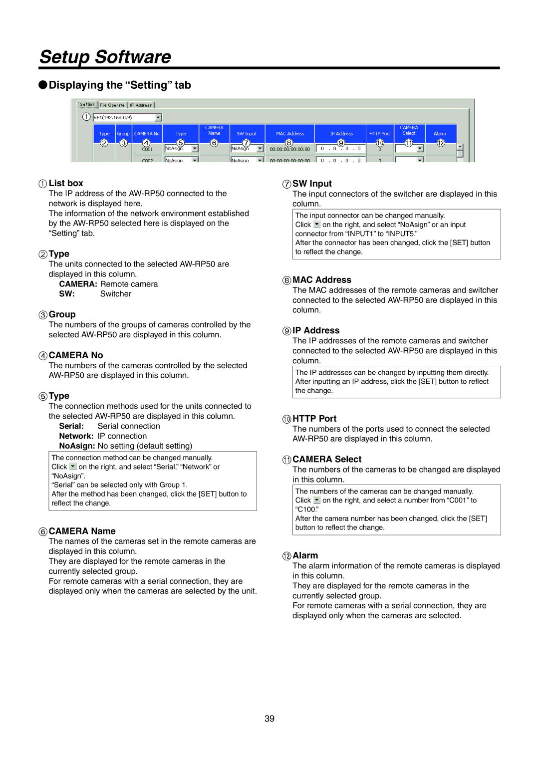
In terms of technology, the AW-RP50N supports multiple communication protocols, including IP (Internet Protocol) and serial communication. This flexibility allows integration with various camera models and third-party systems, offering a cohesive control experience. The unit is designed with robustness in mind, ensuring reliability even in demanding environments.
The AW-RP50N features advanced zoom and focus controls, providing smooth and precise movements essential for capturing high-quality video content. With programmable presets, operators can save specific camera angles and settings, making it easy to quickly switch back to preferred positions during production.
Additionally, it supports HD/SD video formats, catering to diverse production needs. The unit's compact design also makes it an ideal choice for mobile setups and small production teams that require portability without sacrificing performance.
Overall, the Panasonic AW-RP50N remote camera controller is a remarkable piece of technology, combining scalability, ease of use, and high-performance capabilities. Its robust feature set makes it an indispensable asset for professionals in the broadcasting and production industry, ensuring dynamic and reliable control of remote cameras in any situation. Whether scaling a large production or managing a small shoot, the AW-RP50N enables creators to achieve their artistic vision with precision and ease.

