9.2.3.Setting the Inverter PCB, TS PCB and LCD Unit
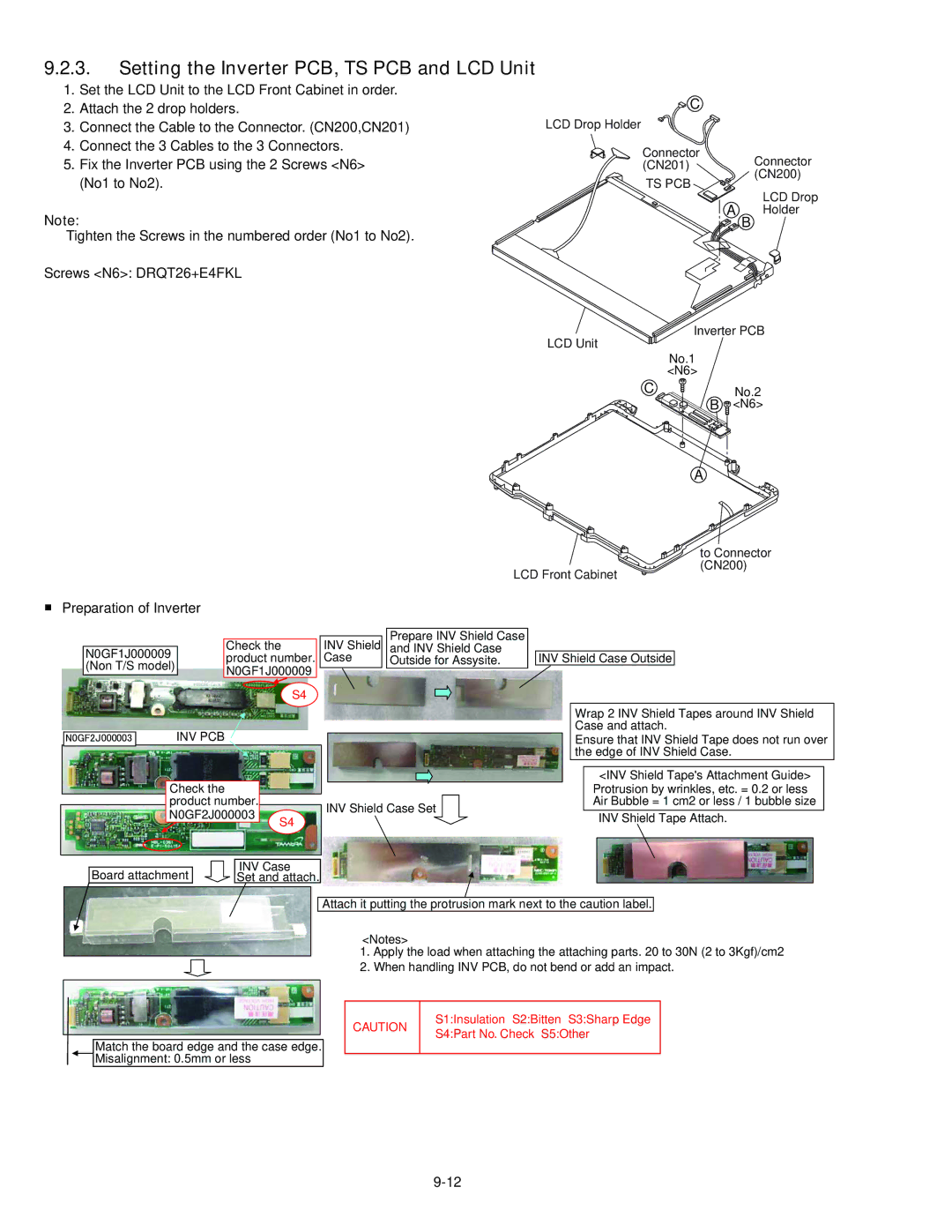
1.Set the LCD Unit to the LCD Front Cabinet in order.
2.Attach the 2 drop holders.
3.Connect the Cable to the Connector. (CN200,CN201)
4.Connect the 3 Cables to the 3 Connectors.
5.Fix the Inverter PCB using the 2 Screws <N6> (No1 to No2).
Note:
Tighten the Screws in the numbered order (No1 to No2).
Screws <N6>: DRQT26+E4FKL
![]() C
C
LCD Drop Holder
Connector
(CN201) Connector (CN200)
TS PCB ![]()
LCD Drop
A B Holder
LCD Unit
![]() Inverter PCB
Inverter PCB
No.1
<N6>
C | No.2 |
B | <N6> |
A
LCD Front Cabinet
■Preparation of Inverter
to Connector (CN200)
|
|
|
|
|
|
|
|
|
| Prepare INV Shield Case |
|
|
|
|
|
|
|
|
| Check the |
|
| INV Shield |
| and INV Shield Case |
|
|
|
|
| |
| N0GF1J000009 |
| product number. |
| Case |
| Outside for Assysite. |
| INV Shield Case Outside |
| |||||
| (Non T/S model) |
| N0GF1J000009 |
|
|
|
|
|
|
|
|
|
|
| |
|
|
|
|
|
|
|
|
|
|
|
| ||||
|
|
|
|
|
|
|
|
|
|
|
|
| |||
|
|
|
|
|
|
|
|
|
|
|
|
|
|
| |
|
|
|
| S4 |
|
|
|
|
|
|
|
|
| ||
|
|
|
|
|
|
|
|
|
|
|
|
|
| Wrap 2 INV Shield Tapes around INV Shield | |
|
|
| INV PCB |
|
|
|
|
|
|
| Case and attach. | ||||
㪥㪇㪞㪝㪉㪡㪇㪇㪇㪇㪇㪊 |
|
|
|
|
|
|
|
| Ensure that INV Shield Tape does not run over | ||||||
|
|
|
|
|
|
|
|
|
|
|
|
|
| the edge of INV Shield Case. | |
Check the |
|
| <INV Shield Tape's Attachment Guide> | |
|
| Protrusion by wrinkles, etc. = 0.2 or less | ||
product number. |
| INV Shield Case Set | Air Bubble = 1 cm2 or less / 1 bubble size | |
N0GF2J000003 | S4 | INV Shield Tape Attach. | ||
|
Board attachment
INV Case
Set and attach.
Attach it putting the protrusion mark next to the caution label.
<Notes>
1.Apply the load when attaching the attaching parts. 20 to 30N (2 to 3Kgf)/cm2
2.When handling INV PCB, do not bend or add an impact.
Match the board edge and the case edge. Misalignment: 0.5mm or less
CAUTION
S1:Insulation S2:Bitten S3:Sharp Edge S4:Part No. Check S5:Other