<N18> |
|
<N16> | to Connector(CN700) |
<N16> | |
<N16> | to Connector(CN701) |
<N16> | <N16> <N16> |
|
Connector |
| |
(CN700) |
| |
Connector | Main Chasis | |
(CN31) | Connector | |
Pet Tape | ||
(CN701) |
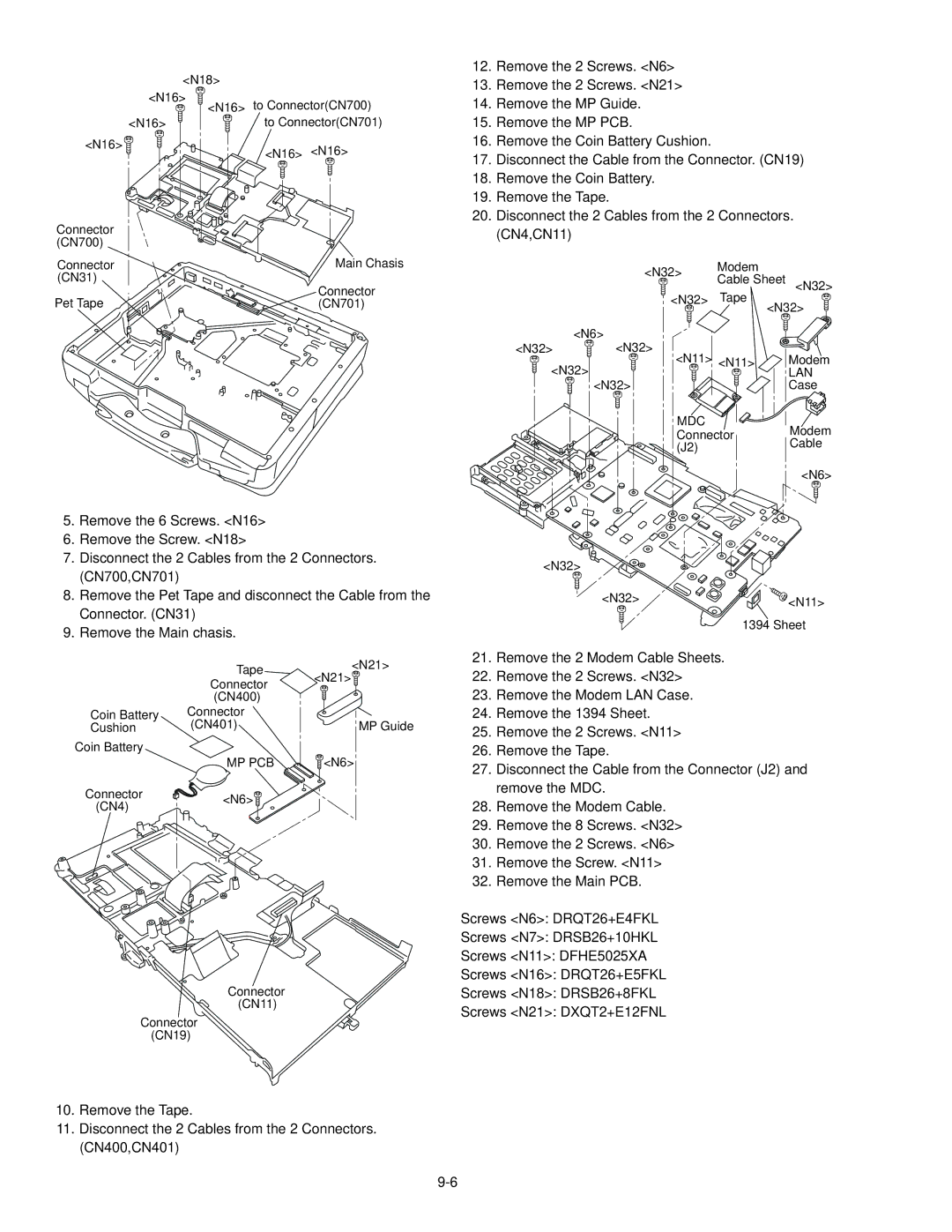
5.Remove the 6 Screws. <N16>
6.Remove the Screw. <N18>
7.Disconnect the 2 Cables from the 2 Connectors. (CN700,CN701)
8.Remove the Pet Tape and disconnect the Cable from the Connector. (CN31)
9.Remove the Main chasis.
| Tape | <N21> |
| <N21> | |
| Connector | |
| (CN400) |
|
Coin Battery | Connector | MP Guide |
Cushion | (CN401) |
Coin Battery
MP PCB | <N6> |
Connector | <N6> | |
(CN4) | ||
|
Connector
(CN11)
Connector (CN19)
12.Remove the 2 Screws. <N6>
13.Remove the 2 Screws. <N21>
14.Remove the MP Guide.
15.Remove the MP PCB.
16.Remove the Coin Battery Cushion.
17.Disconnect the Cable from the Connector. (CN19)
18.Remove the Coin Battery.
19.Remove the Tape.
20.Disconnect the 2 Cables from the 2 Connectors. (CN4,CN11)
| <N32> | Modem |
|
| Cable Sheet | <N32> | |
|
| ||
| <N32> | Tape |
|
|
| <N32> | |
| <N6> |
|
|
<N32> | <N32> |
|
|
| <N11> | <N11> | Modem |
<N32> |
| LAN | |
| <N32> |
| Case |
| MDC |
| Modem |
| Connector | ||
| (J2) |
| Cable |
<N6>
<N32>
<N32> | <N11> |
1394 Sheet
21.Remove the 2 Modem Cable Sheets.
22.Remove the 2 Screws. <N32>
23.Remove the Modem LAN Case.
24.Remove the 1394 Sheet.
25.Remove the 2 Screws. <N11>
26.Remove the Tape.
27.Disconnect the Cable from the Connector (J2) and remove the MDC.
28.Remove the Modem Cable.
29.Remove the 8 Screws. <N32>
30.Remove the 2 Screws. <N6>
31.Remove the Screw. <N11>
32.Remove the Main PCB.
Screws <N6>: DRQT26+E4FKL
Screws <N7>: DRSB26+10HKL
Screws <N11>: DFHE5025XA
Screws <N16>: DRQT26+E5FKL
Screws <N18>: DRSB26+8FKL
Screws <N21>: DXQT2+E12FNL
10.Remove the Tape.
11.Disconnect the 2 Cables from the 2 Connectors. (CN400,CN401)
