|
|
|
|
|
|
|
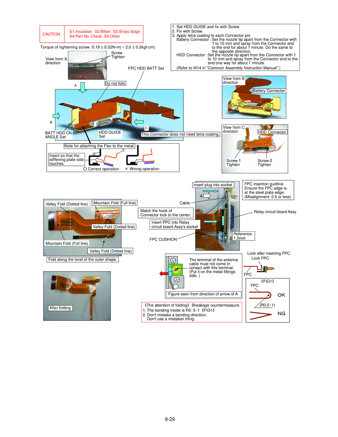
| 1. Set HDD GUIDE and fix with Screw. | |||||
CAUTION |
| S1:Insulation S2:Bitten S3:Sharp Edge |
| 2. Fix with Screw. | |||||||||
| S4:Part No. Check S5:Other |
| 3. Apply tetra coating to each Connector pin. | ||||||||||
|
|
|
|
|
|
|
| Battery Connector : Set the nozzle tip apart from the Connector with | |||||
|
|
|
|
|
|
|
|
| 1 to 10 mm and spray from the Connector end | ||||
Torque of tightening screw :0.19 ± 0.02N·m( 2.0 ± 0.2kgf·cm) |
| ||||||||||||
| to the end for about 1 minute. Do the same to | ||||||||||||
|
|
|
|
| Screw |
| the opposite direction. | ||||||
|
|
|
|
| Tighten | HDD Connector : Set the nozzle tip apart from the Connector with 1 | |||||||
View from A |
|
|
| to 10 mm and spray from the Connector end to the | |||||||||
|
|
|
|
|
| ||||||||
direction |
|
|
|
|
|
| end one way for about 1 minute. | ||||||
|
|
|
|
|
| FPC HDD BATT Set | (Refer to M14 in "Common Assembly Instruction Manual".) | ||||||
|
|
|
|
|
|
|
|
|
|
|
|
|
|
|
|
|
|
|
|
|
|
|
| View from B |
|
| |
|
|
|
|
|
|
|
| direction |
|
| |||
|
|
| 㪘 | Do not fold. |
|
|
|
|
|
|
| ||
|
|
|
|
|
|
|
|
|
|
|
|
| |
|
|
|
|
|
|
|
|
|
|
|
|
|
|
|
|
|
|
|
|
|
|
|
|
|
| Battery Connector |
|
|
|
|
|
|
|
|
|
|
|
| |||
|
|
|
|
|
|
|
|
|
|
|
|
|
|
㪙 |
|
|
|
|
|
|
|
|
|
|
| |
|
|
|
|
|
| 㪚 |
|
| View from C |
|
| |
BATT HDD CN |
| HDD GUIDE |
|
|
|
|
|
| direction |
| HDD Connector | |
|
|
|
|
|
| |||||||
ANGLE Set |
| Set |
| This Connector does not need tetra coating. |
|
|
|
| ||||
|
|
|
|
|
|
|
|
|
|
|
|
|
Note for attaching the Flex to the metal.
Insert so that the |
|
|
stiffening plate side | ||
touches. | Tighten | Tighten |
Correct operation | Wrong operation |
|
Valley Fold (Dotted line) Mountain Fold (Full line)
Valley Fold (Dotted line)
Mountain Fold (Full line)
Insert plug into socket | FPC insertion guidline |
| Ensure the FPC edge is |
A | at the steel plate edge. |
(Misalignment: 0.5 or less) | |
Cable |
|
Match the hook of | Relay circuit board Assy |
Connector lock to the center. |
|
Insert FPC into Relay |
|
circuit board Assy's socket |
|
|
|
|
| Reference |
FPC CUSHION |
|
|
| 1.5mm |
| ||||
|
|
|
|
Valley Fold (Dotted line)
Fold along the level of the outer shape.
After folding
The terminal of the antenna cable must not come in
![]()
![]() contact with this terminal.
contact with this terminal.
(Put it on the metal fittings side. )
Figure seen from direction of arrow of A
The attention of folding :Breakage countermeasure.
1. The bending inside is R0. 5~1 FIG1
2.Don't mistake a bending direction. Don't use a mistaken thing.
Lock after inserting FPC. Lock FPC
FPC
FIG1
FPC
䌏䌋
(R0.5~1)
䌎䌇