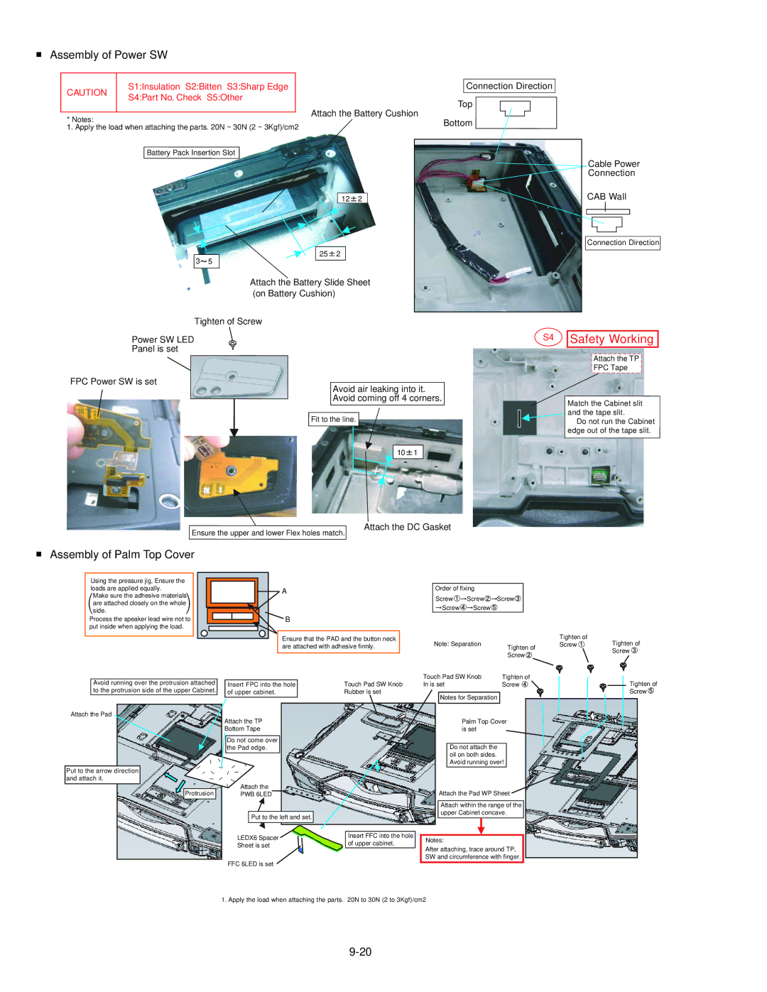
■Assembly of Power SW
CAUTION | S1:Insulation S2:Bitten S3:Sharp Edge | Connection Direction |
S4:Part No. Check S5:Other |
| |
| Top | |
|
|
* Notes: | Attach the Battery Cushion | Bottom | ||
|
|
| ||
1. Apply the load when attaching the parts. 20N ~ 30N (2 ~ 3Kgf)/cm2 |
|
|
| |
Battery Pack Insertion Slot |
|
|
| |
|
|
|
| Cable Power |
|
|
|
| Connection |
|
| 12 | 2 | CAB Wall |
|
|
|
| Connection Direction |
3 | 25 | 2 |
|
|
5 |
|
|
| |
| Attach the Battery Slide Sheet |
| ||
| (on Battery Cushion) |
|
|
|
Tighten of Screw
Power SW LED
Panel is set
FPC Power SW is set
Avoid air leaking into it. Avoid coming off 4 corners.
Fit to the line.
S4
Safety Working
Attach the TP
FPC Tape
Match the Cabinet slit and the tape slit.
Do not run the Cabinet edge out of the tape slit.
Ensure the upper and lower Flex holes match.
10![]() 1
1
Attach the DC Gasket
■Assembly of Palm Top Cover
Using the pressure jig, Ensure the loads are applied equally.
Make sure the adhesive materials are attached closely on the whole side.
Process the speaker lead wire not to put inside when applying the load.
Avoid running over the protrusion attached to the protrusion side of the upper Cabinet.
Attach the Pad
A
![]() B
B
Ensure that the PAD and the button neck are attached with adhesive firmly.
Insert FPC into the hole | Touch Pad SW Knob |
of upper cabinet. | Rubber is set |
| Order of fixing |
|
| |
| Screw | Screw | Screw |
|
| Screw | Screw |
|
|
| Note: Separation | Tighten of | ||
|
|
| ||
|
|
| Screw | |
Touch Pad SW Knob | Tighten of | |||
In is set |
| Screw | ||
Notes for Separation
Tighten of
Screw Tighten of
Screw ![]()
![]()
![]() Tighten of
Tighten of
Screw
Put to the arrow direction and attach it.
Protrusion
Attach the TP
Bottom Tape
Do not come over the Pad edge.
Attach the
PWB 6LED
Put to the left and set.
Palm Top Cover is set
Do not attach the oil on both sides. Avoid running over!
Attach the Pad WP Sheet
Attach within the range of the upper Cabinet concave.
LEDX6 Spacer | Insert FFC into the hole | Notes: | |
Sheet is set | of upper cabinet. | ||
After attaching, trace around TP, | |||
| |||
|
| ||
FFC 6LED is set |
| SW and circumference with finger. | |
|
|
1. Apply the load when attaching the parts. 20N to 30N (2 to 3Kgf)/cm2