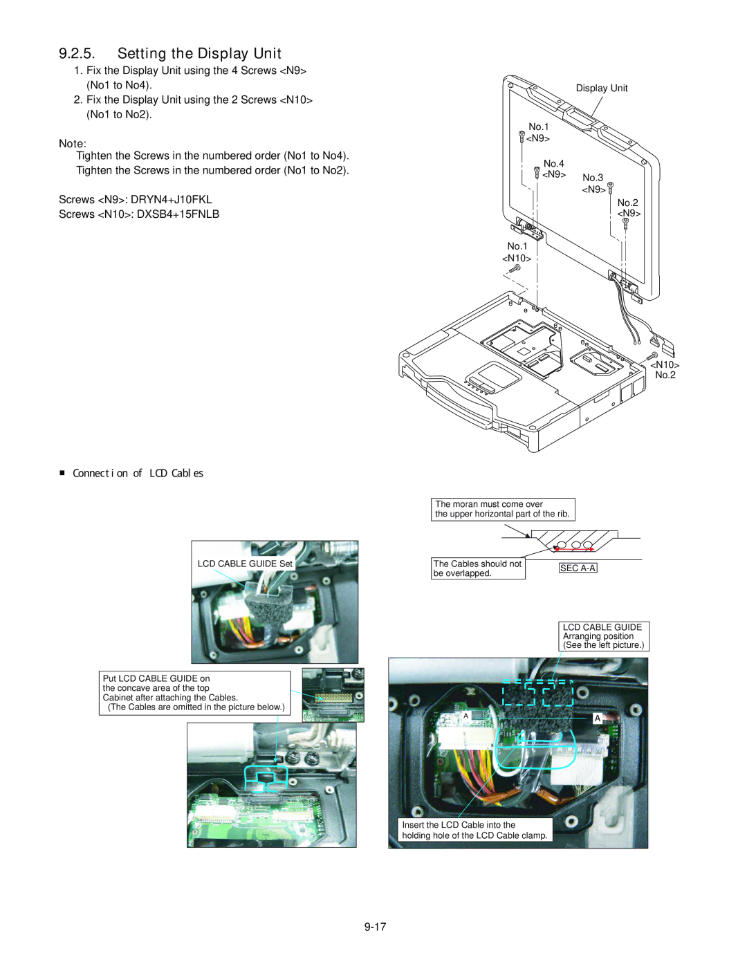
9.2.5.Setting the Display Unit
1.Fix the Display Unit using the 4 Screws <N9> (No1 to No4).
2.Fix the Display Unit using the 2 Screws <N10> (No1 to No2).
Note:
Tighten the Screws in the numbered order (No1 to No4). Tighten the Screws in the numbered order (No1 to No2).
Screws <N9>: DRYN4+J10FKL
Screws <N10>: DXSB4+15FNLB
Display Unit
No.1
![]() <N9>
<N9>
No.4
![]() <N9> No.3
<N9> No.3
<N9> ![]()
No.2
<N9>
No.1
<N10>
![]()
![]()
![]() <N10>
<N10>
No.2
■ Connection of LCD Cables
LCD CABLE GUIDE Set
Put LCD CABLE GUIDE on the concave area of the top Cabinet after attaching the Cables.
(The Cables are omitted in the picture below.)
The moran must come over
the upper horizontal part of the rib.
The Cables should not |
|
|
|
| SEC |
| |
be overlapped. |
|
| |
|
|
|
LCD CABLE GUIDE Arranging position (See the left picture.)
㪘 |
| A |
|
|
|
Insert the LCD Cable into the holding hole of the LCD Cable clamp.
