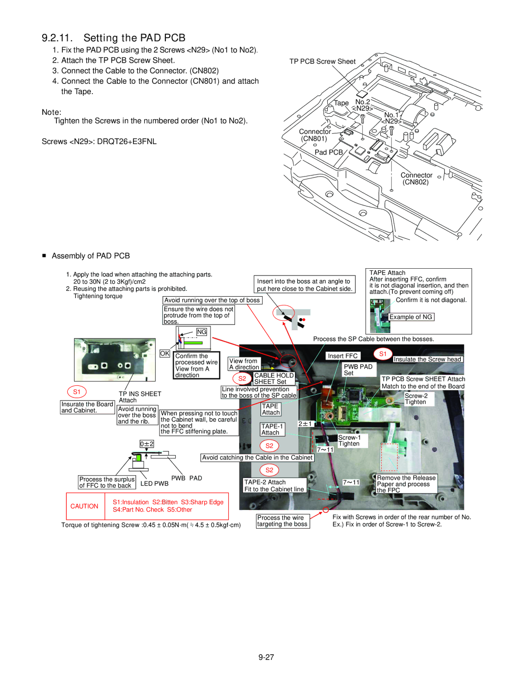
9.2.11.Setting the PAD PCB
1.Fix the PAD PCB using the 2 Screws <N29> (No1 to No2).
2.Attach the TP PCB Screw Sheet.
3.Connect the Cable to the Connector. (CN802)
4.Connect the Cable to the Connector (CN801) and attach the Tape.
Note:
Tighten the Screws in the numbered order (No1 to No2).
Screws <N29>: DRQT26+E3FNL
■Assembly of PAD PCB
TP PCB Screw Sheet
![]()
![]() Tape <No.2N29>
Tape <No.2N29>
Connector ![]() (CN801)
(CN801) ![]()
Pad PCB
No.1 ![]() <N29>
<N29>
Connector (CN802)
1. Apply the load when attaching the attaching parts. |
|
|
|
| TAPE Attach | ||||||
20 to 30N (2 to 3Kgf)/cm2 | Insert into the boss at an angle to | After inserting FFC, confirm | |||||||||
2. Reusing the attaching parts is prohibited. | put here close to the Cabinet side. | it is not diagonal insertion, and then | |||||||||
attach.(To prevent coming off) | |||||||||||
Tightening torque |
|
|
|
|
|
| |||||
Avoid running over the top of boss |
|
|
|
| Confirm it is not diagonal. | ||||||
|
|
| |||||||||
|
|
|
|
|
|
|
|
|
|
| |
| Ensure the wire does not |
|
|
|
|
|
|
|
| ||
|
|
|
|
|
|
|
| ||||
| protrude from the top of |
|
|
|
|
|
| Exam | ple of NG |
| |
| boss. |
|
|
|
|
|
|
|
|
| |
|
|
|
|
|
|
|
| ||||
NG
Process the SP Cable between the bosses.
|
|
|
|
|
|
|
|
|
|
|
|
|
|
| OK |
|
|
|
|
|
|
|
|
|
|
|
|
|
|
|
|
|
|
|
|
|
|
|
|
| S1 |
|
|
|
| ||
|
|
|
|
|
|
|
|
|
|
|
|
|
|
|
| Confirm the |
|
|
|
|
|
|
|
|
|
|
|
|
|
|
| Insert FFC |
|
|
|
|
|
| |||||||||
|
|
|
|
|
|
|
|
|
|
|
|
|
|
|
|
|
|
| processed wire |
| View from |
|
|
|
|
|
|
|
|
|
|
|
|
|
|
|
|
|
| Insulate the Screw head |
| ||||||
|
|
|
|
|
|
|
|
|
|
|
|
|
|
|
|
|
|
|
|
|
|
|
|
|
|
|
|
|
|
|
| PWB PAD |
|
|
| ||||||||||||
|
|
|
|
|
|
|
|
|
|
|
|
|
|
|
|
|
|
|
|
|
|
|
|
|
|
|
|
|
|
|
|
|
|
|
|
|
| ||||||||||
|
|
|
|
|
|
|
|
|
|
|
|
|
|
|
|
|
|
| View from A |
| A direction |
|
|
|
|
|
|
|
|
|
|
|
|
|
|
|
|
|
|
| |||||||
|
|
|
|
|
|
|
|
|
|
|
|
|
|
|
|
|
|
| direction |
| S2 |
| CABLE HOLD |
|
|
|
|
|
|
|
|
| Set |
| TP PCB Screw SHEET Attach | ||||||||||||
|
|
|
|
|
|
|
|
|
|
|
|
|
|
|
|
|
|
|
|
|
|
|
|
|
|
|
|
|
|
|
|
|
| ||||||||||||||
|
|
|
|
|
|
|
|
|
|
|
|
|
|
|
|
|
|
|
|
|
|
| SHEET Set |
|
|
|
|
|
|
|
|
|
|
|
|
| |||||||||||
|
|
|
|
|
|
|
|
|
|
|
|
|
|
|
|
|
|
|
|
|
|
|
|
|
|
|
|
|
|
|
|
|
|
|
|
|
| Match to the end of the Board | |||||||||
S1 |
|
|
|
|
|
|
|
|
|
|
|
|
|
|
|
|
|
|
| Line involved prevention |
|
|
|
|
|
|
|
|
|
|
|
| |||||||||||||||
| TP INS SHEET |
|
|
|
|
|
|
|
|
|
|
|
|
|
|
|
|
|
|
|
|
|
| ||||||||||||||||||||||||
|
|
|
|
|
| to the boss of the SP cable |
|
|
|
|
|
|
|
|
|
|
|
|
|
|
|
| |||||||||||||||||||||||||
|
|
|
|
|
|
|
|
|
|
|
|
|
|
|
|
|
|
|
| ||||||||||||||||||||||||||||
|
|
| Attach |
|
|
|
|
|
|
|
|
|
|
|
|
|
|
|
|
|
|
|
|
|
|
|
|
|
|
|
|
|
| Tighten |
|
| |||||||||||
Insurate the Board |
| Avoid running |
|
|
|
|
|
|
|
|
|
|
| TAPE |
|
|
|
|
|
|
|
|
|
|
|
|
|
|
|
|
|
|
| ||||||||||||||
and Cabinet. |
|
|
|
|
|
|
|
|
|
|
|
| Attach |
|
|
|
|
|
|
|
|
|
|
|
|
|
|
|
|
|
|
|
| ||||||||||||||
|
|
| over the boss | When pressing not to touch |
|
|
|
|
|
|
|
|
|
|
|
|
|
|
|
|
|
|
|
|
|
|
| ||||||||||||||||||||
|
|
| and the rib. | the Cabinet wall, be careful |
|
|
|
|
|
|
|
|
|
|
|
|
|
|
|
|
|
|
|
|
|
|
|
|
| ||||||||||||||||||
|
|
|
|
|
|
|
|
| 2 1 |
|
|
|
|
|
|
|
|
|
|
|
|
|
|
|
| ||||||||||||||||||||||
|
|
|
|
|
|
|
|
|
|
|
|
|
|
| not to bend |
|
|
|
|
|
|
|
|
|
|
|
|
|
|
|
|
|
|
|
|
|
|
| |||||||||
|
|
|
|
|
|
|
|
|
|
|
|
|
|
| the FFC stiffening plate. |
|
|
| Attach |
|
|
|
|
|
|
|
|
|
|
|
|
|
|
|
|
|
| ||||||||||
|
|
|
|
|
|
|
|
|
|
|
|
|
|
|
|
|
|
|
|
|
|
|
|
|
|
|
|
|
|
|
|
|
| ||||||||||||||
|
|
|
|
|
|
|
|
|
|
|
|
|
|
|
|
|
|
|
|
|
|
|
|
|
|
|
|
|
|
|
|
|
|
|
|
|
|
|
|
|
|
|
|
| |||
|
|
|
| 0 2 |
|
|
|
|
|
|
|
|
|
|
|
|
|
| S2 |
|
|
|
|
|
|
| Tighten |
|
|
|
|
|
|
| |||||||||||||
|
|
|
|
|
|
|
|
|
|
|
|
|
|
|
|
|
|
|
|
|
|
|
|
|
|
|
|
|
| ||||||||||||||||||
|
|
|
|
|
|
|
|
|
|
|
|
|
|
|
|
| 7 | 11 |
|
|
|
|
|
| |||||||||||||||||||||||
|
|
|
|
|
|
|
|
|
|
|
|
|
|
|
|
|
|
|
|
|
|
|
|
|
|
|
|
|
|
|
|
|
|
|
|
|
|
|
|
|
|
|
|
| |||
|
|
|
|
|
|
|
|
|
|
|
|
|
|
|
|
|
|
|
|
|
|
|
|
|
|
|
|
|
|
|
|
|
|
|
|
|
|
|
|
| |||||||
|
|
|
|
|
|
|
|
|
|
|
|
|
|
|
|
|
|
|
| Avoid catching the Cable in the Cabinet |
|
|
|
|
|
|
|
|
|
|
|
|
|
| |||||||||||||
|
|
|
|
|
|
|
|
|
|
|
|
|
|
|
|
|
|
|
|
|
|
|
|
|
|
| S2 |
|
|
|
|
|
|
|
|
|
|
|
|
|
|
|
|
| |||
|
|
|
|
|
|
|
|
|
|
|
|
|
|
|
|
|
|
|
|
|
|
|
|
|
|
|
|
|
|
|
|
|
|
|
|
|
|
|
|
|
|
| |||||
| Process the surplus | PWB䇭PAD | ||
| of FFC to the back | LED PWB | ||
|
|
|
| |
CAUTION | S1:Insulation S2:Bitten S3:Sharp Edge | |||
S4:Part No. Check S5:Other | ||||
|
| |||
|
|
|
| |
Torque of tightening Screw :0.45 ± 0.05N·m( 4.5 ± 0.5kgf·cm)
|
|
|
|
|
| Remove the Release |
|
|
| 7 11 |
| Paper and process |
| ||
Fit to the Cabinet line |
|
|
|
| the FPC |
| |
|
| Fix with Screws in order of the rear number of No. | |||||
| Process the wire | ||||||
| targeting the boss | Ex.) Fix in order of | |||||