9.2.15. Setting the W-LAN Module, GPS PCB and Bluetooth PCB
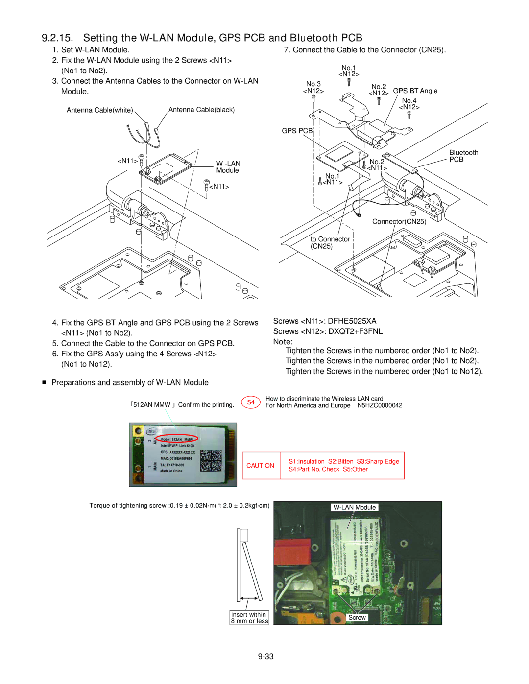
1. | Set |
2. | Fix the |
| (No1 to No2). |
7. Connect the Cable to the Connector (CN25).
No.1
<N12>
3. Connect the Antenna Cables to the Connector on |
Module. |
Antenna Cable(white) | Antenna Cable(black) |
<N11> | W |
| Module |
![]() <N11>
<N11>
No.3
<N12>
GPS PCB
![]() No.1
No.1 ![]() <N11>
<N11>
<N12>No.2 GPS BT Angle
No.4
<N12>
![]()
![]() No.2
No.2 ![]() <N11>
<N11>
Bluetooth
PCB
Connector(CN25) ![]()
to Connector (CN25)
4.Fix the GPS BT Angle and GPS PCB using the 2 Screws <N11> (No1 to No2).
5.Connect the Cable to the Connector on GPS PCB.
6.Fix the GPS Ass’y using the 4 Screws <N12> (No1 to No12).
■Preparations and assembly of
Screws <N11>: DFHE5025XA
Screws <N12>: DXQT2+F3FNL
Note:
Tighten the Screws in the numbered order (No1 to No2). Tighten the Screws in the numbered order (No1 to No2). Tighten the Screws in the numbered order (No1 to No12).
512AN MMW Confirm the printing. | S4 | How to discriminate the Wireless LAN card | |
For North America and Europe N5HZC0000042 | |||
|
CAUTION
S1:Insulation S2:Bitten S3:Sharp Edge S4:Part No. Check S5:Other
Torque of tightening screw :0.19 ± 0.02N·m( 2.0 ± 0.2kgf·cm)
Insert within 8 mm or less
Screw