Network Camera
Introduction
For operation assistance Call
For assistance, please call
Trademarks
Network Camera Memo
Important Safety Instructions
Table of Contents
Index 133
Specifications and Troubleshooting 111
Technical Guides
Section
Main Features
Getting to Know Network Camera
Authentication
Multi-Client Access
Update Firmware
Multi-Camera Screen
System Requirements
Authentication-System Security Feature
Authentication window
Self Bonding tape Connector Cover
Included Accessories
Setup CD-ROM 1 pc Rubber Cap 1 pc
AC Adaptor 1 pc Flexible Stand 1 pc Sunshade 1 pc
Setup CD-ROM
Front View
Camera Feature Locations
Lens Cover Indicator
Fixed Focus Lens
Rear View
Bottom View
Network Camera Setup
Installation Procedure
Type 2-Internet Connection with a Broadband Router
Network Camera Configuration Type
Network Camera can be installed on the LAN/Intranet
Type 3-Internet Direct Connection with a Modem
Type 4-Direct Connection with a PC
How to turn on Network Camera for Installation
Network parameters memo for Network Camera
Network Parameters
Preparing the Network Parameters for Network Camera
Network Parameters Table
Network Camera Configuration Type
Default
Type Port No
How to refer the network parameters from the PC
Click OK to close IP Configuration window
Setting IP Address of the PC in Type 4 Configuration Type
Private IP address
Proxy Server Setting
Operating Instructions
Simple Installation using the Setup CD-ROM
Operating Instructions
Operating Instructions
Click the language to change the display
To set up the wireless network parameters
Wireless Setup
To access Network window
Channel
Connection and Signal Strength status
Set Infrastructure Default or AdHoc
Encryption Password window
Encryption Key window
Default Key
Wireless Settings
If Top Page does not appear
Network Camera Access from the Internet
Port Forwarding IP Masquerade feature
Top
Network Camera Screen and Setup Window
Network Camera Flow Chart
Http//Global IP address of Broadband RouterPortNo Top
Top
Example
Multi-Camera
Motion Jpeg
Single Camera
Help
ActiveX Controls
Single Camera Screen
Click to Center
Using Operation Bar
Using Pan/Tilt Operation
Setting Preset Positioning and Home Positioning
Deleting the preset buttons
Click Delete
Non Transfer mode Alarm/Timer mode
Viewing Buffered Image Screen
Primary
Viewer
Clicking Start Capture
Secondary
Multi-Camera Screen
Setup
Setup
Name/Time
Administrator
Go to Top
Security
External Output
Indicator Control
Reset to Factory
Control
Go to Top
Network
Instructions for the data fields
Enter only the number
Host Name When your ISP uses the Dhcp server function which
If you use Network Camera on the LAN, set up
Check Dhcp Dynamic Host Configuration Protocol
Or administrator for the Host name
File size of the image
Name
Name/Time
Camera
Date
Auto
Adjustment
Time Changed AM/PM or 24H
Time Zone
Click Security Administrator on Setup
Security Administrator
Refer to page 65 for details about authentication security
For Setup Password
Enable
Administrator and General User Authentication window
Retype
Click Security General User on Setup
Security General User
Operating Instructions
Top View Image
Image
Resolution
Instructions for the data fields Top
160 x
Image Transfer
Non Transfer mode
Transfer in the Alarm Mode
Click Alarm on Image Transfer window
Alarm enable condition
Active Time of Trigger
Login timing
Over write setting
Data transfer method
Setting Example
Setting explanation
Transfer in the Timer Mode
Buffers or transfers by the timer trigger
Image Frequency Sets the interval to send the image
Login timing
Over write setting
Fixed Indoor
Camera Setup
Instructions for the data fields White Balance
Fixed
Having reached the selected end
White Balance is also registered in preset programming
Suggested
Tilt Range
Click Save when finished
Specifying the Pan/Tilt range
Multi-Camera
URL * 1 or Host
Enable check box
IP Address or
Camera Name
Click External Output Control on Setup
External Output Control
Indicator Control
Status
Click Restart Now
Click Cancel to quit. The window returns to Setup
Restart
Update Firmware
Click Update Firmware on Setup
Click Update Firmware
Open
Reset to Factory Default
Technical Guides
Network Camera Installation
Outdoor Installation
High performance for wireless communication
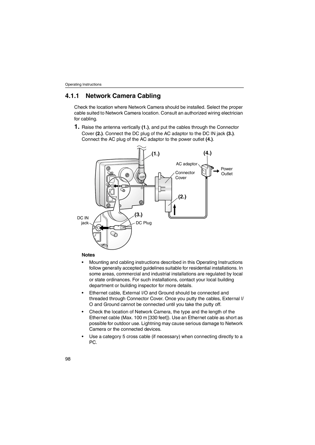
Network Camera Cabling
Be sure to thread the AC adaptor cord through the hook
Do not cover Ventilation hole 100
Cover the putties by rolling
Inches
Flexible Stand Mounting
Attach Network Camera to the tripod using the tripod bolt
Network Camera Mounting
Tripod Mounting
Waterproof the rest of the cable Self Bonding tape 102
Wall Mounting
Stand if necessary
Waterproof the rest Cable For assistance, please call 103
Ceiling Mounting
Caulk around Flexible Stand if necessary
Top Bottom
Making holes on mortar wall
Pin Function
Interfacing to the External I/O
Explanation of External I/O
External Sensor Input
Circuit Diagram Example
Space, , , #, &, %, =, +, ?, , and are not available
Ascii and ISO-8859-1 Character Table
Unavailable character set
108
Displayable character set
For assistance, please call 109
Maintenance
110
Specifications and Troubleshooting
For assistance, please call 111
Network Camera Reset Procedure-Default Settings
112
Default Settings List
For assistance, please call 113
114
Items Factory Default Indispensable setting Value Alarm
For assistance, please call 115
Timer
116
Items Factory Default Indispensable setting Value Timer
117
Control Indicator Control
118
Other Specification Description
Specifications
Network Camera Specifications Description
Mm 3.46 inches
Weight 570 1.26 lb. Only the unit
Message Transferring Method
Excluding the antenna and protruding objects
Problem Cause and Remedy
Troubleshooting
About Network Camera Setup
When you use DDNS, you need to set Default Gateway
Proxy server may prevent you from connecting directly to
When Top Page does not appear, port number 80 might not be
If Top Page does not appear in the above procedure, press
Transfers older
For Indicator Control window
Network window on
124
About Network Camera Setup Problem Cause and Remedy
Refer to page 91 for the Update Firmware
About Top View Image screen
Lens
View Image Setting window on
About Other Troubles
Confirmation of Network Camera Operation
Click the language to change the display
FCC and Other Information
Medical
Encryption WEP
Glossary
AdHoc
Ieee 802.11b
132
Index
133
Operating Instructions
TCP/IP
Wireless Router 37 Wireless window 136
137
For product service
When you ship the product