|
| Scanning | Dot clock |
| Plug and play | |||
| Number of | frequency |
| |||||
|
|
|
|
| ||||
Display mode |
|
| frequency | Format |
|
|
| |
displayed dots |
|
|
| |||||
| H (kHz) | V (Hz) | (MHz) |
| RGB2 | |||
|
|
| ||||||
|
|
|
|
|
|
| EDID1 | EDID2 |
MAC21 | 1 152 × 870 | 68.7 | 75.1 | 100 | RGB/DVI | ◯ |
| ◯ |
1 280 × 768 | 1 280 × 768 | 39.6 | 49.9 | 65.3 | RGB/DVI |
|
|
|
1 280 × 768 | 47.8 | 59.9 | 79.5 | RGB/DVI |
|
|
| |
|
|
|
| |||||
1 280 × 800 | 1 280 × 800 | 41.3 | 50 | 68 | RGB/DVI |
|
|
|
1 280 × 800 | 49.7 | 59.8 | 83.5 | RGB/DVI |
|
|
| |
|
|
|
| |||||
MSXGA | 1 280 × 960 | 60 | 60 | 108 | RGB/DVI |
|
|
|
| 1 280 × 1 024 | 52.4 | 50 | 88 | RGB/DVI |
|
|
|
| 1 280 × 1 024 | 64 | 60 | 108 | RGB/DVI | ◯ |
| ◯ |
SXGA | 1 280 × 1 024 | 72.3 | 66.3 | 125 | RGB/DVI |
|
|
|
1 280 × 1 024 | 78.2 | 72 | 135.1 | RGB/DVI |
|
|
| |
|
|
|
| |||||
| 1 280 × 1 024 | 80 | 75 | 135 | RGB/DVI | ◯ |
| ◯ |
| 1 280 × 1 024 | 91.1 | 85 | 157.5 | RGB/DVI |
|
|
|
| 1 400 × 1 050 | 65.2 | 60 | 122.6 | RGB/DVI | ◯ |
| ◯ |
SXGA+ | 1 400 × 1 050 | 78.8 | 72 | 149.3 | RGB/DVI |
|
|
|
| 1 400 × 1 050 | 82.2 | 75 | 155.9 | RGB/DVI |
|
|
|
WXGA+ | 1 440 × 900 | 55.9 | 59.9 | 106.5 | RGB/DVI |
|
|
|
UXGA | 1 600 × 1 200 | 75 | 60 | 162 | RGB/DVI | ◯ |
| ◯ |
WSXGA+ | 1 680 × 1 050 | 65.3 | 60 | 146.3 | RGB/DVI |
|
|
|
1 920 × 1 080*1 | 1 920 × 1 080 | 66.6 | 59.9 | 138.5 | RGB/DVI |
|
|
|
|
|
|
|
|
|
|
|
|
WUXGA*1 | 1 920 × 1 200 | 74 | 60 | 154 | RGB/DVI | ◯ |
| ◯ |
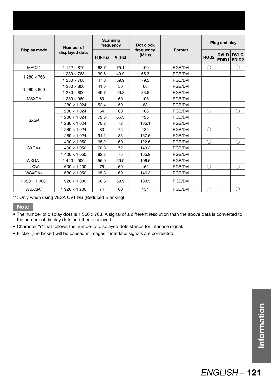
*1: Only when using VESA CVT RB (Reduced Blanking)
Note
•The number of display dots is 1 366 x 768. A signal of a different resolution than the above data is converted to the number of display dots and then displayed.
•Character “i” that follows the number of displayed dots stands for interlace signal.
•Flicker (line flicker) will be caused in images if interlace signals are connected.
Information
