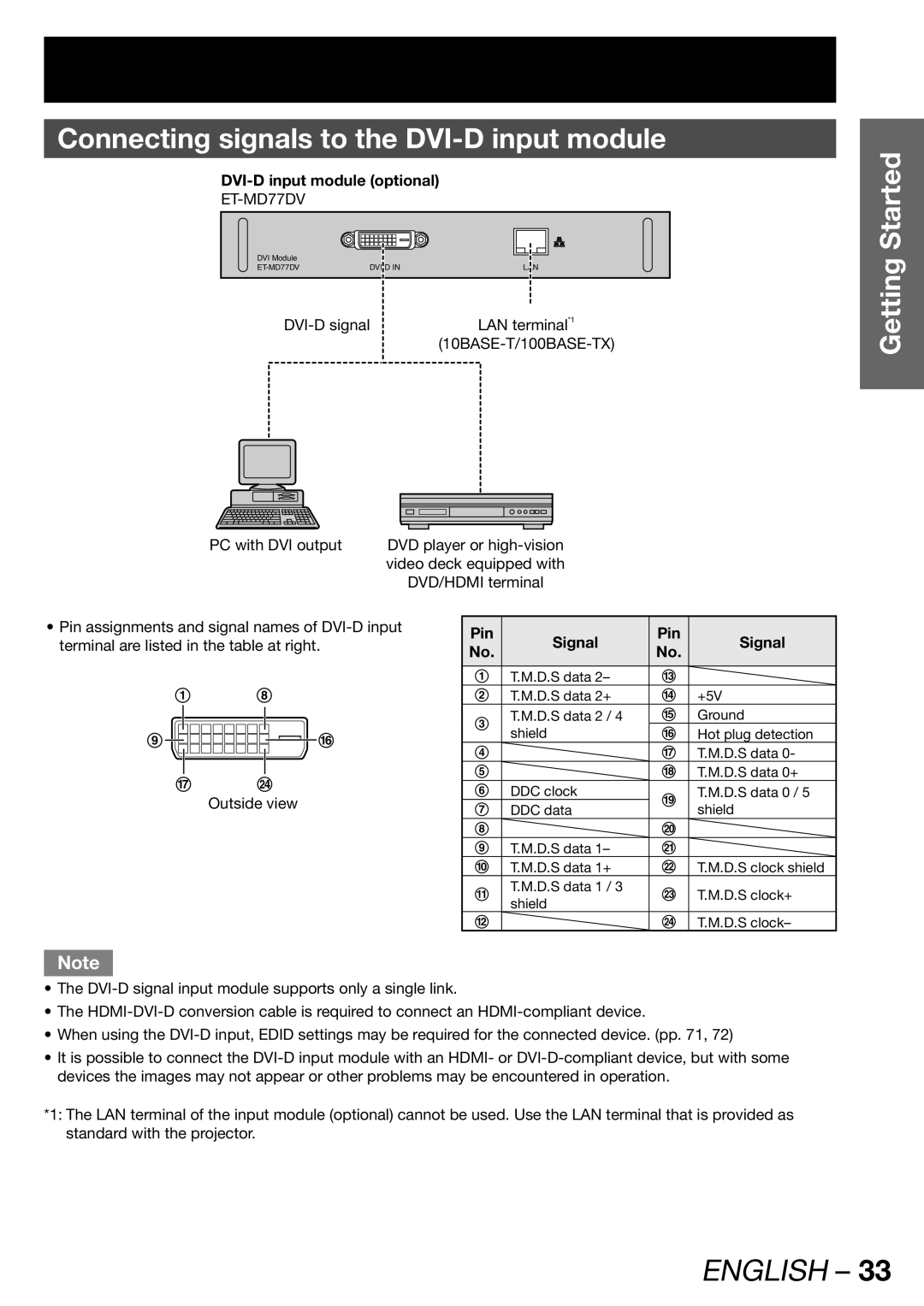
Connecting signals to the DVI-D input module
DVI-D input module (optional)
DVI Module |
|
|
LAN | ||
LAN terminal*1 | ||
|
| |
PC with DVI output | DVD player or |
| video deck equipped with |
| DVD/HDMI terminal |
Getting Started
•Pin assignments and signal names of
1 8
9![]()
![]() p
p
qx
Outside view
Pin | Signal | Pin | Signal | |
No. | No. | |||
|
| |||
|
|
|
| |
1 | T.M.D.S data 2– | m |
| |
2 | T.M.D.S data 2+ | n | +5V | |
3 | T.M.D.S data 2 / 4 | o | Ground | |
shield | p | Hot plug detection | ||
| ||||
4 |
| q | T.M.D.S data 0- | |
5 |
| r | T.M.D.S data 0+ | |
6 | DDC clock | s | T.M.D.S data 0 / 5 | |
7 | DDC data | shield | ||
| ||||
8 |
| t |
| |
|
|
|
| |
9 | T.M.D.S data 1– | u |
| |
j | T.M.D.S data 1+ | v | T.M.D.S clock shield | |
k | T.M.D.S data 1 / 3 | w | T.M.D.S clock+ | |
| shield |
|
| |
l |
| x | T.M.D.S clock– |
Note
•The
•The
•When using the
•It is possible to connect the
*1: The LAN terminal of the input module (optional) cannot be used. Use the LAN terminal that is provided as standard with the projector.
