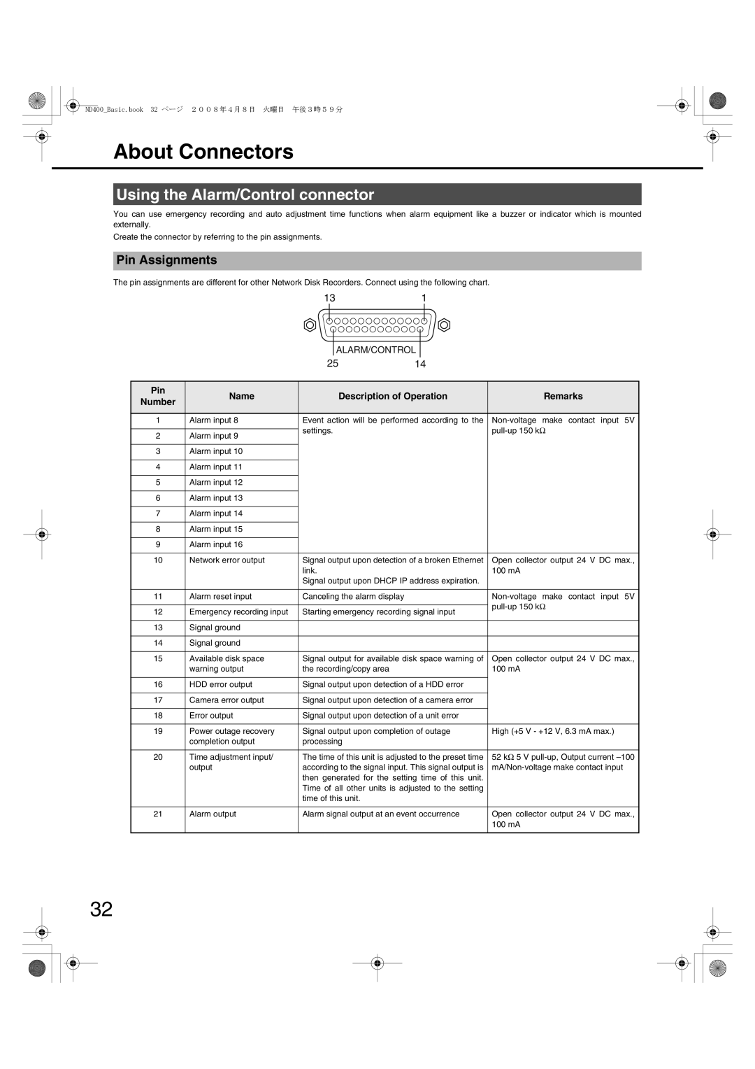
WJ-ND400 specifications
The Panasonic WJ-ND400 is a robust network video recorder (NVR) designed for reliable and scalable surveillance solutions. It serves as a central component in a modern security system, enabling the management and storage of video data from IP cameras. This device is particularly well-suited for a variety of applications, ranging from small retail setups to large enterprise installations.One of the key features of the WJ-ND400 is its impressive storage capacity, supporting up to 16 terabytes of internal storage. This allows for extended recording times and the ability to retain high-resolution video footage without sacrificing quality. It supports various video compression formats, such as H.264 and H.265, which optimize file sizes and bandwidth use while maintaining clarity.
The WJ-ND400 boasts an intuitive user interface that facilitates seamless configuration and management of the recording settings. Users can access the device through a web browser, providing a convenient way to monitor live feeds, playback recorded footage, and manage camera settings from anywhere with an internet connection. This remote access feature is critical for businesses that require flexible surveillance management.
In terms of connectivity, the NVR supports Power over Ethernet (PoE), allowing for simplified installations by reducing the need for additional power supplies for IP cameras. The WJ-ND400 also utilizes a 10/100/1000 BASE-T Ethernet interface that ensures high-speed data transfer, optimizing the performance of connected devices.
Moreover, the WJ-ND400 is compatible with a wide range of Panasonic IP cameras, enhancing its versatility within a surveillance setup. It supports up to 64 channels of video input, enabling integration of multiple cameras for comprehensive coverage of surveillance areas.
Advanced features include motion detection and scheduled recording, allowing users to customize recording parameters based on specific needs. The NVR can also provide event alerts and notifications, enhancing its capability to respond to security incidents in real time.
In conclusion, the Panasonic WJ-ND400 stands out for its powerful storage capabilities, user-friendly interface, and extensive compatibility with various cameras. Its efficient use of high-quality video compression, combined with robust networking features, makes it an optimal choice for organizations looking to enhance their security infrastructure.

