Setting of external synchronization switch
When an external synchronizing signal input is provided to the external synchronization input connector on the rear side of the camera for loop through, select
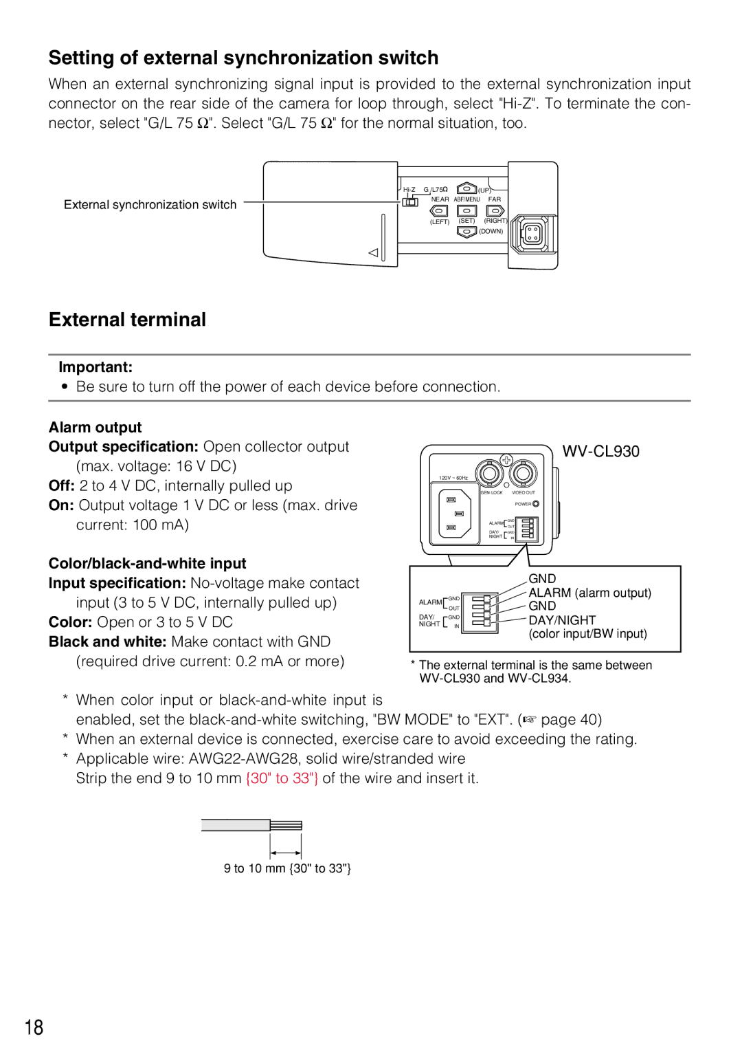
External synchronization switch
(UP) | |
NEAR | ABF/MENU FAR |
(LEFT) (SET) (RIGHT) ![]() (DOWN)
(DOWN)
External terminal
Important:
• Be sure to turn off the power of each device before connection.
Alarm output
Output specification: Open collector output (max. voltage: 16 V DC)
Off: 2 to 4 V DC, internally pulled up
On: Output voltage 1 V DC or less (max. drive current: 100 mA)
WV-CL930
120V ~ 60Hz
VIDEO OUT |
POWER ![]()
ALARM | GND |
| OUT |
DAY/ | GND |
NIGHT | IN |
Color/black-and-white input
Input specification:
Color: Open or 3 to 5 V DC
Black and white: Make contact with GND (required drive current: 0.2 mA or more)
|
|
|
|
|
| GND |
ALARM |
| GND |
|
|
| ALARM (alarm output) |
DAY/ |
| OUT |
|
|
| GND |
|
|
|
| |||
| GND |
|
|
| DAY/NIGHT | |
NIGHT |
| IN |
|
|
| |
|
|
|
|
|
| (color input/BW input) |
|
|
|
|
|
| |
|
|
|
|
|
|
*The external terminal is the same between
*When color input or
enabled, set the
*When an external device is connected, exercise care to avoid exceeding the rating.
*Applicable wire:
9 to 10 mm {30" to 33"}
18