Adjustment of phase in VBS genlock mode (VBS)
The adjusting video signal of the camera and the criterial external synchronizing input signal are connected to a
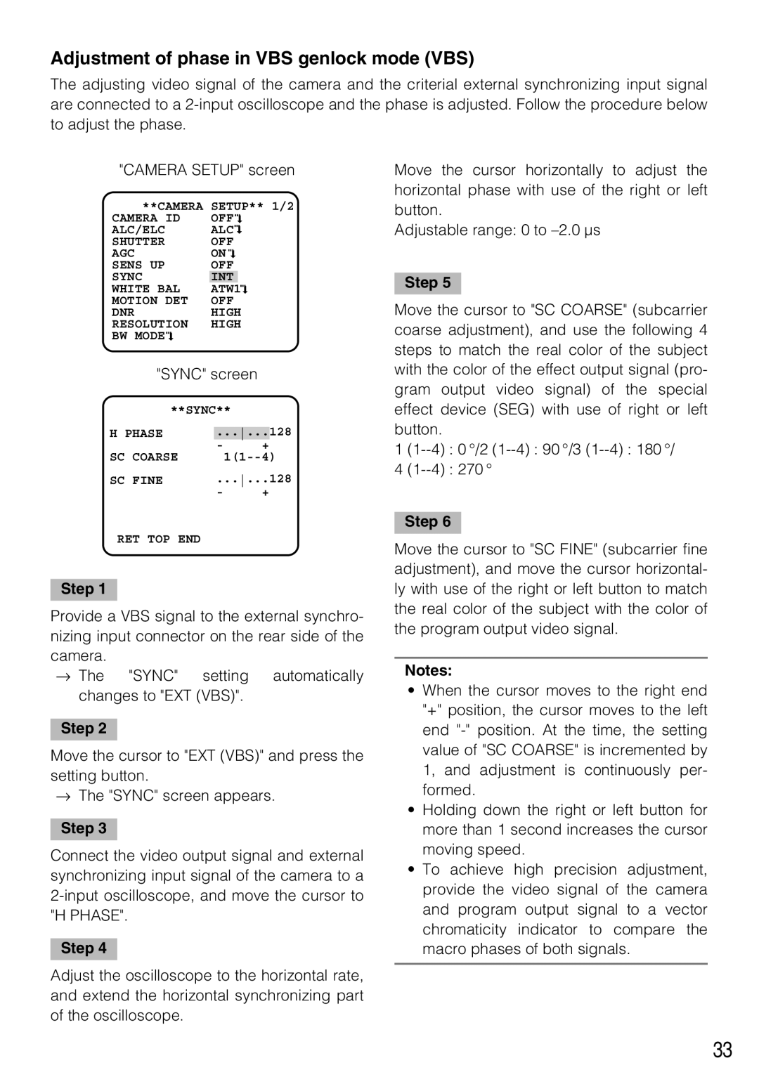
"CAMERA SETUP" screen
**CAMERA | SETUP** 1/2 | ||||||||
CAMERA ID | OFF |
|
|
| |||||
|
| ||||||||
ALC/ELC | ALC |
|
| ||||||
| |||||||||
| |||||||||
SHUTTER | OFF | ||||||||
AGC | ON |
|
| ||||||
| |||||||||
| |||||||||
SENS UP | OFF | ||||||||
SYNC | INT |
|
|
|
| ||||
WHITE BAL | ATW1 |
|
|
|
| ||||
|
|
|
| ||||||
MOTION DET | OFF | ||||||||
DNR | HIGH | ||||||||
RESOLUTION | HIGH | ||||||||
BW MODE |
|
|
|
|
|
|
|
|
|
|
|
|
|
|
|
|
| ||
|
|
|
|
|
|
|
| ||
"SYNC" screen
**SYNC**
H PHASE | ...... | 128 | ||
|
| - | + |
|
SC | COARSE |
| ||
SC | FINE | ......128 | ||
|
| - | + |
|
Move the cursor horizontally to adjust the horizontal phase with use of the right or left button.
Adjustable range: 0 to
Step 5
Move the cursor to "SC COARSE" (subcarrier coarse adjustment), and use the following 4 steps to match the real color of the subject with the color of the effect output signal (pro- gram output video signal) of the special effect device (SEG) with use of right or left button.
1
4
RET TOP END
Step 1
Provide a VBS signal to the external synchro- nizing input connector on the rear side of the camera.
→ The "SYNC" setting automatically changes to "EXT (VBS)".
Step 2
Move the cursor to "EXT (VBS)" and press the setting button.
→The "SYNC" screen appears.
Step 3
Connect the video output signal and external synchronizing input signal of the camera to a
Step 4
Adjust the oscilloscope to the horizontal rate, and extend the horizontal synchronizing part of the oscilloscope.
Step 6
Move the cursor to "SC FINE" (subcarrier fine adjustment), and move the cursor horizontal- ly with use of the right or left button to match the real color of the subject with the color of the program output video signal.
Notes:
•When the cursor moves to the right end "+" position, the cursor moves to the left end
•Holding down the right or left button for more than 1 second increases the cursor moving speed.
•To achieve high precision adjustment, provide the video signal of the camera and program output signal to a vector chromaticity indicator to compare the macro phases of both signals.
33