Installation | Applicable | Recommend- | Screw | Minimum |
position | mounting base | ed screw | quantity | strength (per 1 screw) |
|
|
|
|
|
On ceiling | M6 | 4 pieces | 196 N {44 lbf} | |
|
|
|
|
|
| M8 | 3 pieces | 196 N {44 lbf} | |
|
|
|
|
|
| M6 | 3 pieces | 196 N {44 lbf} | |
|
|
|
|
|
On wall | M8 | 4 pieces | 921 N {207 lbf} | |
|
|
|
|
|
| M6 | 3 pieces | 2.25 kN {505 lbf} |
For some applicable mounting bases, "A" is attached to the model number. The mounting con- ditions are the same even for the
•When the tripod socket is mounted on the top of the camera, be sure to use the screws that were removed from the tri- pod socket. Use of longer or shorter screws may cause drop or damage. (Recommended tightening torque: 0.39 N·m {0.29 lbf·ft})
![]() Screws
Screws
Tripod socket hole: | Tripod socket |
|
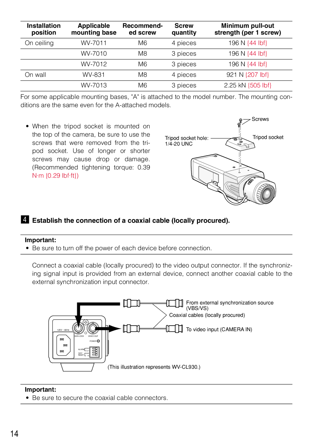
vEstablish the connection of a coaxial cable (locally procured).
Important:
•Be sure to turn off the power of each device before connection.
Connect a coaxial cable (locally procured) to the video output connector. If the synchroniz- ing signal input is provided from an external device, connect another coaxial cable to the external synchronization input connector.
120V ~ 60Hz
VIDEO OUT |
POWER ![]()
ALARM | GND |
| OUT |
DAY/ | GND |
NIGHT | IN |
From external synchronization source (VBS/VS)
Coaxial cables (locally procured)
To video input (CAMERA IN)
(This illustration represents
Important:
• Be sure to secure the coaxial cable connectors.
14