Adjustment of phase in power supply synchronization mode (LL)
The adjusting video signal of the camera and the criterial external synchronizing input signal are connected to a
Note:
Movement of the camera or presence of a spike noise in the power line may cause vertical phase change. In such a case, adjust the phase again.
Follow the procedure in the next page to adjust the phase.
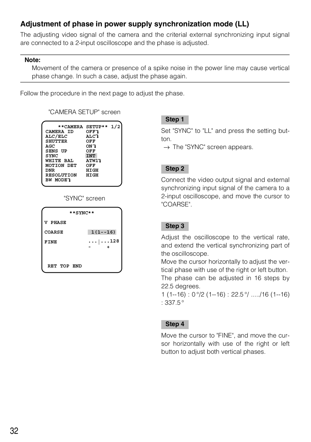
"CAMERA SETUP" screen
**CAMERA | SETUP** 1/2 | ||||||||
CAMERA ID | OFF |
|
|
| |||||
|
| ||||||||
|
| ||||||||
ALC/ELC | ALC |
|
| ||||||
| |||||||||
| |||||||||
SHUTTER | OFF | ||||||||
AGC | ON |
|
| ||||||
| |||||||||
| |||||||||
SENS UP | OFF | ||||||||
SYNC | INT |
|
|
|
| ||||
WHITE BAL | ATW1 |
|
|
|
| ||||
|
|
|
| ||||||
|
|
|
| ||||||
MOTION DET | OFF | ||||||||
DNR | HIGH | ||||||||
RESOLUTION | HIGH | ||||||||
BW MODE |
|
|
|
|
|
|
|
|
|
|
|
|
|
|
|
|
| ||
|
|
|
|
|
|
|
| ||
"SYNC" screen
| **SYNC** | |||
V PHASE |
|
|
|
|
COARSE |
|
|
|
|
|
|
| ||
FINE | ......128 | |||
| - | + |
| |
RET TOP END
Step 1
Set "SYNC" to "LL" and press the setting but- ton.
→The "SYNC" screen appears.
Step 2
Connect the video output signal and external synchronizing input signal of the camera to a
Step 3
Adjust the oscilloscope to the vertical rate, and extend the vertical synchronizing part of the oscilloscope.
Move the cursor horizontally to adjust the ver- tical phase with use of the right or left button. The phase can be adjusted in 16 steps by 22.5 degrees.
1
: 337.5 °
Step 4
Move the cursor to "FINE", and move the cur- sor horizontally with use of the right or left button to adjust both vertical phases.
32