DMD15/DMD15L
Page
Latest Software Revision Confirmation
Warranty Period
Warranty and Service
Warranty Coverage Limitations
Warranty Replacement and Adjustment
Non-Warranty Repair
Warranty Repair Return Procedure
Radyne, Inc
Revision Date Reason for Change Level
TM051 Record of Revisions
DMD15/DMD15L IBS/IDR Satellite Modem TM051 Rev
Table of Contents
Operation
DMD15/DMD15L IBS/IDR Satellite Modem Table of Contents
User Interfaces
Electrical Interfaces
Appendices
DMD15/DMD15L Available Options
Description
Internal High Stability
Reed-Solomon Codec
Turbo Codec
Internal Engineering Service Channel ESC
Drop and Insert D&I
5 8PSK Modulation
Customized Options
Back Panel Options
Page
Removal and Assembly
Installation Requirements
Unpacking
Mounting Considerations
DMD15/DMD15L Initial Configuration Check
Modulator Checkout
Initial Power-Up
Modulator
Qpsk
Terminal Setup
Theory of Operation
DMD15/DMD15L Functional Block Diagram
Operation DMD15/DMD15L IBS/IDR Satellite Modem
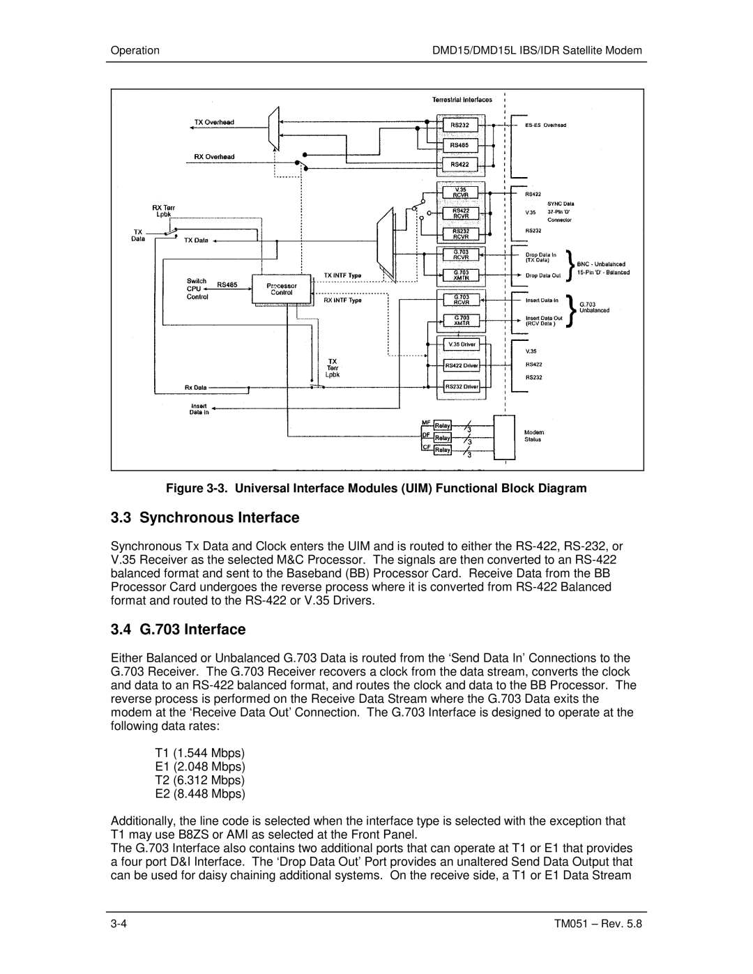
Universal Interface Module UIM
Universal Interface Modules UIM Dip Switch Settings
G.703 Interface
Synchronous Interface
Terrestrial Loopback
Open Collector Faults
Modem Status
Form-C Contacts
Loopback Functional Block Diagram
Loopback Functional Block Diagram
Baseband Processing
Baseband Processor Card
Tx Baseband Processing
Clock Selection
Rx Baseband Processing
Monitor & Control M&C Subsystem
Asynchronous Serial Port #1
Front Panel Interface
Watchdog Timer
Clock
Program Flash ROM
11 DMD15/DMD15L Clocking Options
Demodulator
Scte Serial Clock Transmit External
SCT Serial Clock Transmit
SCR Serial Clock Receive
IDI Insert Data
EXT if REF External if Reference
Transmit Timing
Transmit RS-422 or V.35 Interface
Loop Timing
14.2 G.703 Interface or Asymmetrical Data Rates
Receive
Looped Modems
Insert Only
Drop Only
PCM-30
Mode Selection
PCM-30C
PCM-31
16.5 T1-D4/T1-D4-S
PCM-31C
16.6 T1-ESF/ T1-ESF-S
SLC-96
SATCh TS Enter to Edit
Drop and Insert Mapping
Example
Map Copy
RX Edit RX Active
TX Edit TX Active
TX Active TX Edit
RX Active RX Edit
Operation in the DMD15/DMD15L
Reed-Solomon Codec Refer to Figures 3-14, 3-15, and Table
Reed-Solomon Code Rate
Interleaving
15. Reed-Solomon Decoder Functional Block Diagram
IDR
19 DMD15 Automatic Uplink Power Control Aupc Operation
8PSK
Function Description
Aupc Functions
Kbps Baud Rate Example for Standard IBS Enhanced Mode
DMD15/DMD15L IBS/IDR Satellite ModemOperation
Asynchronous Multiplexer Mode
Standard IBS Mode
ESC Backward Alarms
Reacquisition
To Disable the ESC Backward Alarms
16. Reacquisition flow in the DMD15/DMD15L
DMD15/DMD15L IBS/IDR Satellite Modem Operation TM051 Rev
Page
Front Panel User Interface
User Interfaces
LCD Front Panel Display
Edit Mode Key Functions Front Panel Only
Cursor Control Arrow Keys
Numeric Keypad
Parameter Setup
Front Panel LED Indicators
LED
Mode IDR, IBS, Closed Net, Drop & Insert
Modulator Demodulator Interface Monitor Alarms System Test
Front Panel Control Screen Menus
Main Menus
IBS Mode
QPSK, BPSK, OQPSK, 8PSK, 16QAM
Allows the user to select the framing type
Used with IDR, IBS, or Asynchronous Interface Only
Strap Code Refer to Strap Code Guide, .3, Table
Demodulator Menu Options and Parameters
Demodulation
Swp Delay 900.0 sec
Swp Bound ±0 32 kHz
ReAcq Sweep 32000 Hz
CSC
ESC CH#1
Interface Menu Options and Parameters
ESC CH#2
Time Mark Enable, Disable
Tx D&I menu Drop Mode Enable, Disable
SATCh TS
Async menu ES Mode Normal, Enhanced option
Rx D&I menu Insert Mode Enable, Disable
Clk Polarity Normal, Inverted
T1E1 Frm Src Internal, External
Aupc Menu Options and Parameters
Local CL Action
Tracking Rate
HOLD, NOMINAL, Maximum
Remote CL Action
OFF, on
Monitor Menu Options and Parameters
SER
Cber
Alarms Menu Options and Parameters
TxSynth Mask Pass/Fail, No/Yes
CompClk Mask Pass/Fail, No/Yes
Major Rx menu RxuProc Mask Pass/Fail, No/Yes
SigLoss Mask Pass/Fail, No/Yes
Indicates status of the Tx Reed-Solomon Fifo
RS Fifo
User InterfacesDMD15/DMD15L IBS/IDR Satellite Modem
RAM/ROM
Indicates M&C memory fault
RxIFSynLock RxOSPLLLock Buf Clk Lock
IBS BER
UProc Ext Ref Lock Backward Alr menu
YY MM DD
System Menu Options and Parameters
Hhmmss
Test Menu Options and Parameters
DMD15/DMD15L Strap Codes
Reed Code Rate
DMD15/DMD15L Strap Codes Data
Insert
DEC
1544
104 576 16/15
None CNT
Sample DMD15/DMD15L Applications
IBS
Operational Case Examples
Closed Network
Case 1 IDR 8.448 Mbps, 3/4 Rate Viterbi
Case 2 IBS 1.544 Mbps, 3/4 Rate Viterbi
Demodulator Method
Case 4 Loop Timing Example Method
Case 3 Closed Network, 3/4 Rate Viterbi, IBS Overhead
Data Rate
Configuring the DMD15/DMD15L for Drop and Insert
Terrestrial Framing Drop Mode/Insert Mode
Operational Mode
Insert Terrestrial Frame Source
4 D&I Sample Configurations and D&I Clock Setup Options
DMD15/DMD15L IBS/IDR Satellite Modem User Interfaces
Transmit Trunk and Receive Trunk
Single Trunk
D&I Maps and Map Editing
ROM
D&I ROM Maps T1/E1 Time Slot
User Interfaces DMD15/DMD15L IBS/IDR Satellite Modem
Modem Terminal Mode Control
Terminal Mode Control
Modem Setup for Terminal Mode
Protocol Wrapper
Protocol Structure
Sync
Byte Count
Source ID
Byte Field Data Content Running Checksum
Destination ID
Frame Sequence Number
Frame Description and Bus Handshaking
Global Response Operational Codes
DMD15 Response Error Code Descriptions
Response Opcodes Response Opcode Description
Mparmmodulationtypeerror
Mparmextrefsourceerror
Mparmconvencodererror
Mparmreedsolomonerror
Mparmnotimplementederror
Mparmsymbolrateerror
Mparmtransfertypeerror
Mparmsummaryfaulterror
Dparmdescramblercontrolerror
Dparmdifferentialdecodererror
Dparmdescramblertypeerror
Dparmspectrumerror
Collision Avoidance
Directly-Addressed Equipment Multi-Drop Override ID
Flow Control and Task Processing
Software Compatibility
Rllp Summary
Sync Count SRC Dest FSN Opcode Data Checksum Addr Bytes
Remote Port Packet Structure
DEST. ID
FSN
Modem Command Set
3 DMD15/DMD15L Opcode Command Set
Command Opcode
Command
User InterfacesDMD15/DMD15L IBS/IDR Satellite Modem
Detailed Command Descriptions 4.9.5.1 DMD15/DMD15L Modulator
Query Response
Configuration Bytes
= INTELSAT, 1 = EUTELSAT, 2 = Closed NET1
T1 ESF S
User Interfaces DMD15/DMD15L IBS/IDR Satellite Modem
Status Bytes
Alarm
Online Flag
Opcode 240Bh Query a Modulator’s Status
DMD15/DMD15L IBS/IDR Satellite Modem User Interfaces
Opcode 2405h Query a modulator’s latched alarms
Opcode 2601h Command a modulator’s configuration
T1 ESF S
DMD15/DMD15L IBS/IDR Satellite Modem User Interfaces
User Interfaces DMD15/DMD15L IBS/IDR Satellite Modem
Satellite
Opcode 2606h Command a modulators modulation type
Opcode 2618h Command a modulators baseband loopback
Opcode 262Ah Command Aupc Remote Enable
5.2 DMD15/DMD15L Demodulator
T1 ESF S
DMD15/DMD15L IBS/IDR Satellite Modem User Interfaces
User Interfaces DMD15/DMD15L IBS/IDR Satellite Modem
Unsigned Binary Value, 0-99, Implied Decimal Point
User Interfaces DMD15/DMD15L IBS/IDR Satellite Modem
DMD15/DMD15L IBS/IDR Satellite Modem User Interfaces
Query Response
DMD15/DMD15L IBS/IDR Satellite Modem User Interfaces
User Interfaces DMD15/DMD15L IBS/IDR Satellite Modem
Bits 4 7 = Spares
Opcode 2406h Query a demodulator’s latched alarms
Query Response
Bit 4 = E1 FAS alarm received = Received
T1 ESF S
User Interfaces DMD15/DMD15L IBS/IDR Satellite Modem
DMD15/DMD15L IBS/IDR Satellite Modem User Interfaces
Opcode 2A0Dh Command a demodulator’s descrambler control
Opcode 2A15h Command a demodulator’s T1E1 frame source
Modem Queries & Commands
Opcode 2407h Query a modems latched alarms
Query Response
DMD15/DMD15L IBS/IDR Satellite Modem User Interfaces
Opcode 240Fh Query date Query Response
Opcode 240Eh Query time Query Response
Opcode 2C05h Command set date
Opcode 2C04h Command set time
102
DMD15/DMD15L G.703 Interface Module w/ESC
DMD15/DMD15L Connections
AC Power Input Module
Power Inputs
DC Power Input Module
RX J2
TX J1
SD J3
DDO J4
Sync Data J8
Async J9
Status J11
S6 AGC Out/Prompt C Switch Positions
Prompt C
Terminal J12
S6 Ground/Deferred C Switch Positions AGC Out
Remote J13
ESC 8K Data J15
ESC Voice J16
ESC Alarms J17
Switch J18
Escaud RX 2A
Escaud RX 1A
TXD-A BWI
MOD FLT
DDO-B RT-B
Sync TT-B
IDO-B RD-B
TX-B BWI
Sync CS-B
Sync DM-B
RXO-B
Sync RS-B
Page
Troubleshooting
Periodic Maintenance
DMD15/DMD15L Fault Philosophy
Active Alarms 6.2.2.1 Major Alarms
Alarm Masks
Minor Alarms
Latched Alarms
TM051 Rev
DMD15/DMD15L TX Fault Matrix
IBS Fault Conditions and Actions
Interpreting the Matrices
Fault Detected From Satellite Across Interface E
TM051 Rev
Demodulator Specifications
Modulator Specifications
FEC
Monitor and Control
Plesiochronous Buffer
DMD15/DMD15L Drop and Insert Optional
Universal Interface
Terrestrial Interfaces
Environmental
Physical
DMD15 Data Rate Limits
IBS IDR
10 DMD15 BER Specifications
BER
10-6 10-7 10-8
10-6 10.5 dB 10-7 10.8 dB 10.4 dB 10-8 11.0 dB 10.7 dB
Page
Page
Page
Valid Values for k
Appendix a Reed-Solomon Codes
TM051 Rev
TM051 Rev
TM051 Rev
TM051 Rev
TM051 Rev
TM051 Rev
TM051 Rev
TM051 Rev
TM051 Rev
Page
Page
AGC
ADC
AIS
Amsl
DCE
DAC
Dpll
DTE
IBS
Hssi
Ieee
Iess
MIB
Mfas
Nvram
PLL
ROM
RAM
SEQ
Sync
Misc
Y Z
16QAM
8PSK