SmartLink | 2 • SmartLink installation |
|
|
Installing the M-ATA
1The unit should be installed in a dry environment with at least 2 inches (5 cm) of clearance at the sides, front, and rear of the unit to allow air circulation for cooling.
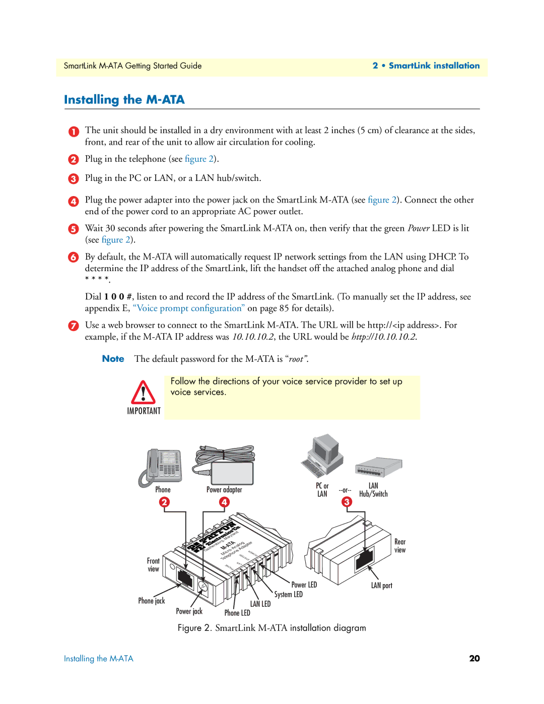
2Plug in the telephone (see figure 2).
3Plug in the PC or LAN, or a LAN hub/switch.
4Plug the power adapter into the power jack on the SmartLink
5Wait 30 seconds after powering the SmartLink
6By default, the
* * * *.
Dial 1 0 0 #, listen to and record the IP address of the SmartLink. (To manually set the IP address, see appendix E, “Voice prompt configuration” on page 85 for details).
7Use a web browser to connect to the SmartLink
Note The default password for the
Follow the directions of your voice service provider to set up voice services.
IMPORTANT
Phone | Power adapter | PC or | LAN | ||
LAN | Hub/Switch | ||||
|
|
|
2 | 4 | 3 |
| Maryland | |
| Gaithersburg, |
|
|
| |
| M | |
| Micro | POWER |
Front | Telephone SYSTEM | |
PHONE | LAN | |
view |
| |
|
| |
| Power LED | |
Phone jack | System LED | |
LAN LED | ||
Power jack | ||
Phone LED |
Rear view
LAN port
Figure 2. SmartLink M-ATA installation diagram
Installing the | 20 |