3.2 Back Panel
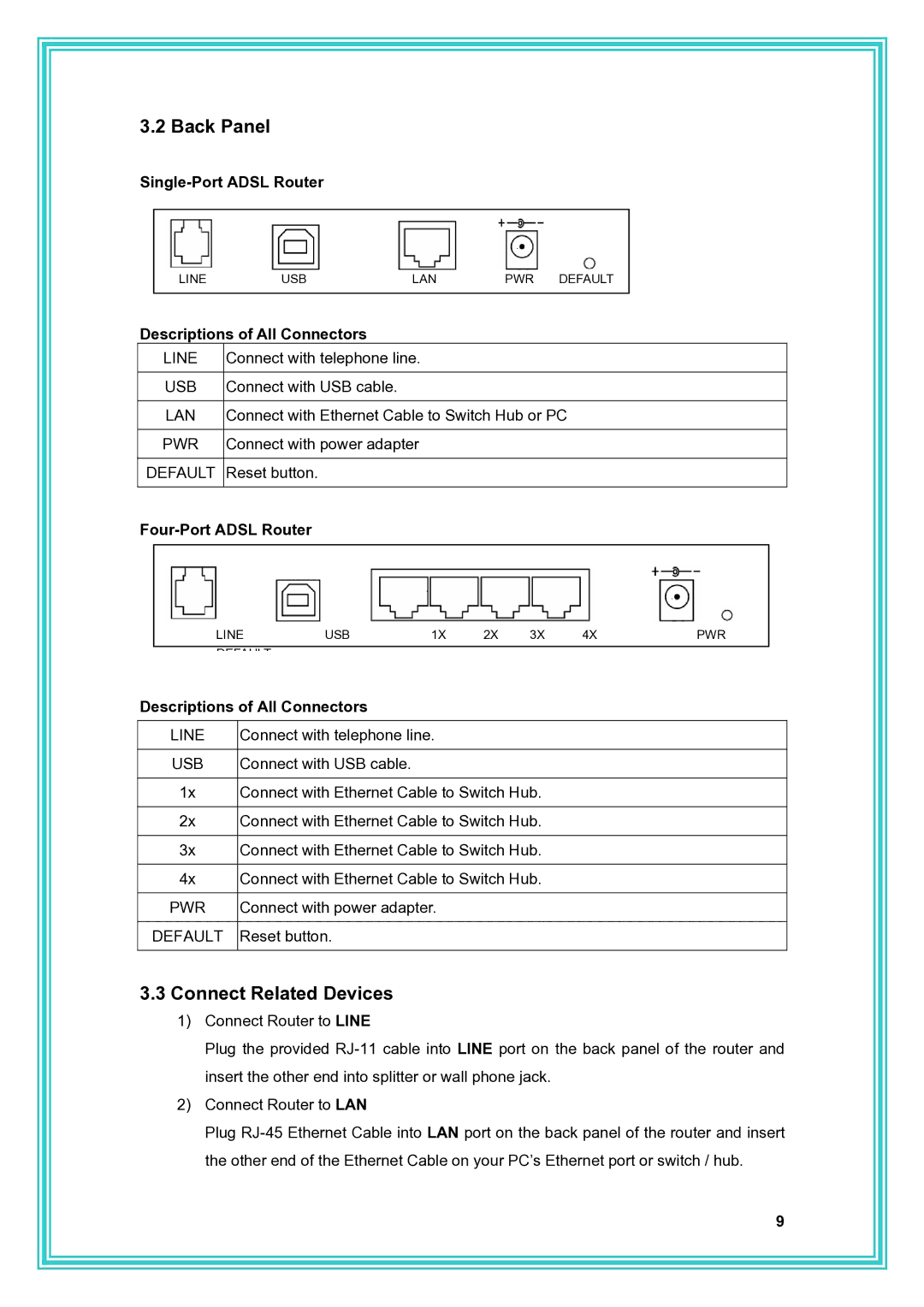
Single-Port ADSL Router
LINEUSBLANPWR DEFAULT
Descriptions of All Connectors
LINE | Connect with telephone line. |
|
|
USB | Connect with USB cable. |
|
|
LAN | Connect with Ethernet Cable to Switch Hub or PC |
|
|
PWR | Connect with power adapter |
|
|
DEFAULT | Reset button. |
|
|
Four-Port ADSL Router
LINE | USB | 1X | 2X | 3X | 4X | PWR |
|
|
|
|
|
|
|
DEFAULT |
|
|
|
|
|
|
Descriptions of All Connectors
LINE | Connect with telephone line. |
|
|
USB | Connect with USB cable. |
|
|
1x | Connect with Ethernet Cable to Switch Hub. |
|
|
2x | Connect with Ethernet Cable to Switch Hub. |
|
|
3x | Connect with Ethernet Cable to Switch Hub. |
|
|
4x | Connect with Ethernet Cable to Switch Hub. |
|
|
PWR | Connect with power adapter. |
|
|
DEFAULT | Reset button. |
|
|
3.3Connect Related Devices
1)Connect Router to LINE
Plug the provided
2)Connect Router to LAN
Plug
9