SPMS | Page 23 of 32 |
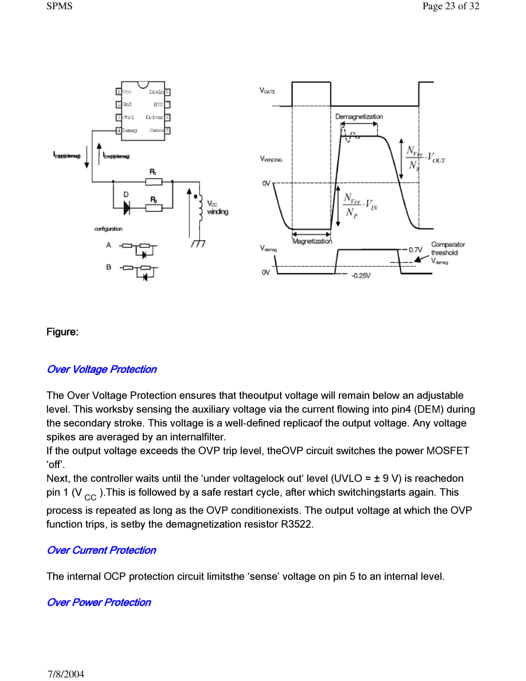
Figure:
Over Voltage Protection
The Over Voltage Protection ensures that theoutput voltage will remain below an adjustable level. This worksby sensing the auxiliary voltage via the current flowing into pin4 (DEM) during the secondary stroke. This voltage is a
If the output voltage exceeds the OVP trip level, theOVP circuit switches the power MOSFET ‘off’.
Next, the controller waits until the ‘under voltagelock out‘ level (UVLO = ± 9 V) is reachedon pin 1 (V CC ).This is followed by a safe restart cycle, after which switchingstarts again. This process is repeated as long as the OVP conditionexists. The output voltage at which the OVP function trips, is setby the demagnetization resistor R3522.
Over Current Protection
The internal OCP protection circuit limitsthe ‘sense’ voltage on pin 5 to an internal level.
Over Power Protection
7/8/2004
