SC3127 N321 | 213 | 18 | 2 | 64 | 0 | - | - |
SC3132 N321 | 223 | 222 | 43 | 40 | 0 | - | - |
SC3132 N331 | 223 | 222 | 43 | 40 | 0 | - | - |
*Option Byte Data for these models was not available at manual release. Refer to future updates to this manual regarding these models.
Tuner
Note: Described alignments are only necessary when the NVM (part reference number7602) is replaced.
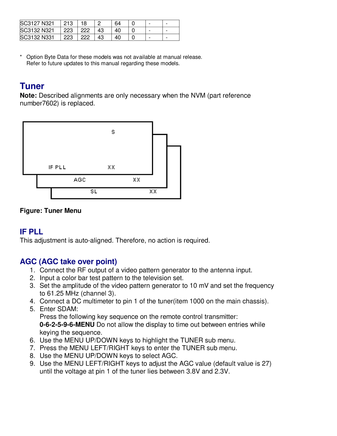
Figure: Tuner Menu
IF PLL
This adjustment is
AGC (AGC take over point)
1.Connect the RF output of a video pattern generator to the antenna input.
2.Input a color bar test pattern to the television set.
3.Set the amplitude of the video pattern generator to 10 mV and set the frequency to 61.25 MHz (channel 3).
4.Connect a DC multimeter to pin 1 of the tuner(item 1000 on the main chassis).
5.Enter SDAM:
Press the following key sequence on the remote control transmitter:
6.Use the MENU UP/DOWN keys to highlight the TUNER sub menu.
7.Press the MENU LEFT/RIGHT keys to enter the TUNER sub menu.
8.Use the MENU UP/DOWN keys to select AGC.
9.Use the MENU LEFT/RIGHT keys to adjust the AGC value (default value is 27) until the voltage at pin 1 of the tuner lies between 3.8V and 2.3V.