SPMS | Page 6 of 32 |
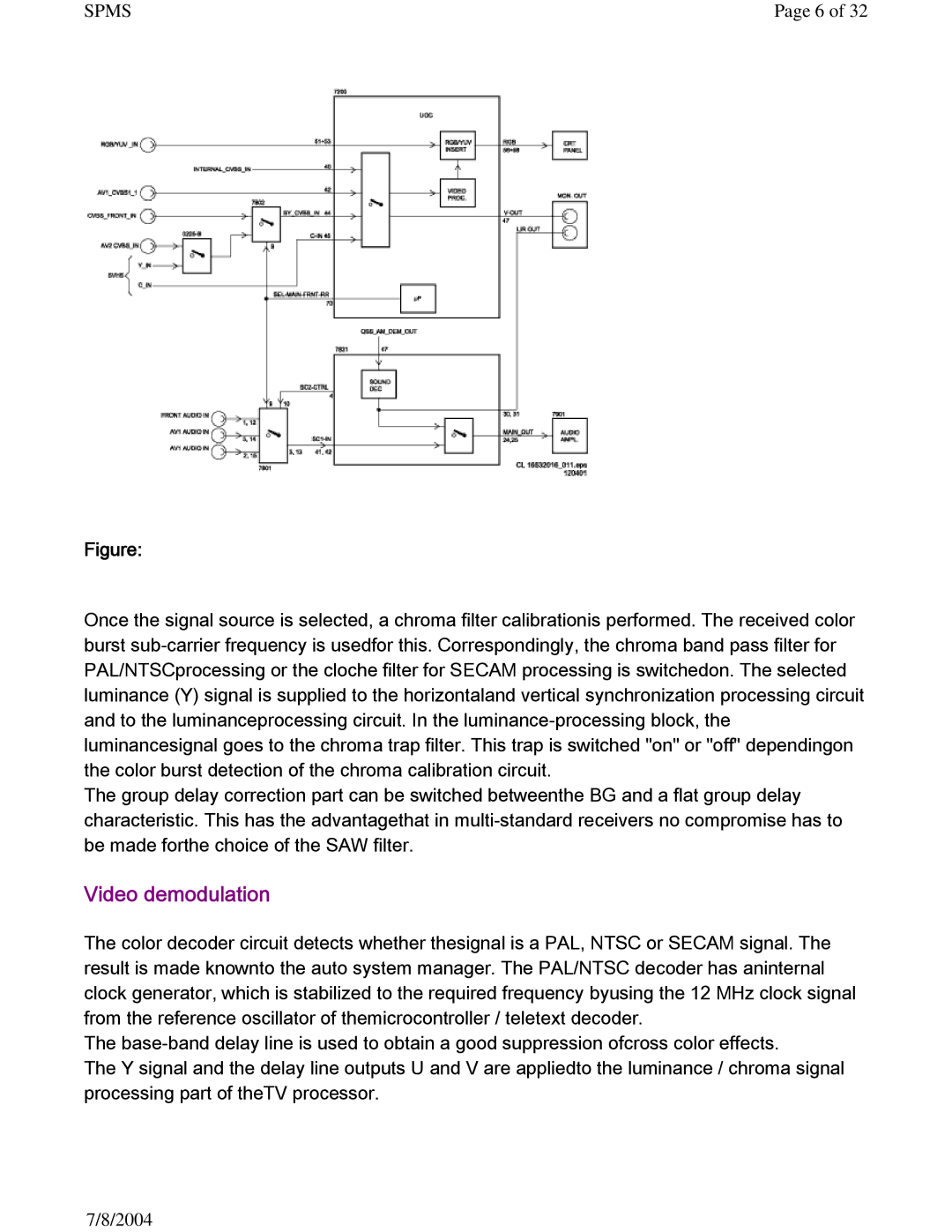
Figure:
Once the signal source is selected, a chroma filter calibrationis performed. The received color burst
The group delay correction part can be switched betweenthe BG and a flat group delay characteristic. This has the advantagethat in
Video demodulation
The color decoder circuit detects whether thesignal is a PAL, NTSC or SECAM signal. The result is made knownto the auto system manager. The PAL/NTSC decoder has aninternal clock generator, which is stabilized to the required frequency byusing the 12 MHz clock signal from the reference oscillator of themicrocontroller / teletext decoder.
The
The Y signal and the delay line outputs U and V are appliedto the luminance / chroma signal processing part of theTV processor.
7/8/2004