DVD-Video
Region management information
Freesat HD tuners built-in
Features
How to replace the fuse
Accessories
Sales and Support Information
Before use
Table of Contents
Music
Convenient Functions
Reference
HDD Hard disk drive Handling Care
Remote Control Information
Remote Control Information/Unit Care
Using the remote control
Unit Care
Location of Parts/Controls
Remote Control
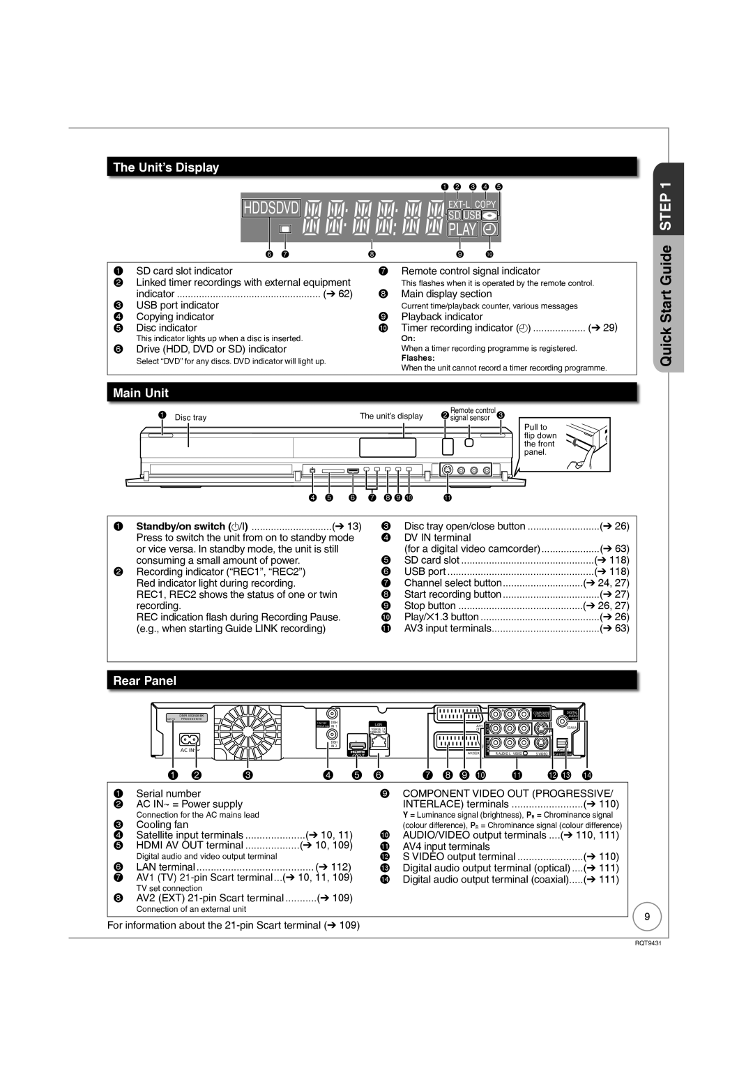
Unit’s Display
Main Unit
Rear Panel
Connecting with a Panasonic TV Viera
When your Television has an Hdmi input terminal
Basic Connection
Regarding Viera Link Hdavi ControlTM function
Hdmi features
After completing the connections, proceed to the TV Tuning
When the unit is not to be used for a long time
Tips
This unit
When your Television does not have an Hdmi input terminal
To turn the unit on
Auto Set Up freesat
Enter your Postcode
Quick
Repeat step to enter PIN again to confirm
Power Save Function e, r to select On or Off, then
Enter your Name
Enter new PIN
To change PIN 104, Owner ID
To set the clock manually
Hour Minute Second Day Month Year
To select Search Mode To select the search mode
Tuning in Other Satellite Services
Q to select the desired satellite
To select Channel Type
To continue the Auto Setup
To start the Auto Setup
To select the channel type
Delete unwanted channels
HDD and Disc Information
Timer record
Instant record
HDDDiscs
Teletext and Digital Text Mheg cannot be recorded
Recording and copying programmes
HDD and discs you can use for recording and play
HDD and Disc Handling
Regarding 8 cm Disc
Discs that cannot be played
Play-only discs
Types of disc for the type of connected TV
Following disc can be played
USB Memory and Card Handling
Setting the protection
USB memories you can use on this unit
Cards usable on this unit
To turn the unit on Few times and select freesat, then
Watching Television freesat
To select current programme, then To select View, then
To select desired channel
Selecting a channel without using the channel list
Watching Television of the Other Satellite Service
To turn the unit on Few times and select Other Sat., then
To select the desired channel, then
Few times to select the HDD or DVD drive
Playback
Stopping Play
W, q to select an item, then
Recording Television Programmes HDD
Pausing Recording Stopping Recording
To start recording
Press h Press g
To cancel a timer recording programming
Timer Recording Using the TV Guide freesat HDD
Various function with freesat
TV Guide list appears
To select the HD programme for recording, then
To select Single Timer Rec., then
To go to step above
Recording the ITV HD, etc. programme
Copying Titles
Set the recording mode
To select Copy, then
Set the copy direction
Register titles for copy
Set other settings
R to select Start Copying, then Q to select Yes, then
Finalise or Create Top Menu
To select Delete, then
Deleting Titles
To select the title, then
Delete Navigator
Important Notes for Recording
Broadcasting
Image such as wide
DR File Conversion
High Speed Copy
Recording modes
Advanced Recording
Programmes simultaneous recording
FR Flexible Recording Mode
Recording modes and approximate recording time
Regarding recording time remaining
To select the title to play, then
Hold for about 1 second
Specifying the Recording Time
Direct TV Recording
Operation during Recording
To select New Timer
Advanced Timer Recording HDD
Programme, then
To move through the items
W, q to select the desired genre, then
To select Series Timer Rec., then
W, q to select the desired programme, then
Series recording
Then e, r to select the programme
To select Yes, then
2a DEL to delete
W, q to make changes
After performing step Previous
Programme
Recorded
What is the TV Guide system?
Using the TV Guide list
TV Guide system freesat
To display
Few times to select freesat, then
List of channel genre
To select the desired item
Advanced Playback
To select the title you want to watch, then
Selecting Titles to Play
During playback PLAY/x1.3 Press and hold
Frame-by-Frame Viewing Display the subtitle during play
To select the time, then
Time Slip
Manual Skip
Insert a disc or SD card To select Play Video AVCHD, then
Playback of the High Definition Video Avchd and playlists
W, q to select the title, then
With the unit stopped To select Others, then
Playing DivX
Playing DivX video contents
Insert a disc or USB memory
To select Play Video DivX, then
Regarding DivX VOD content
Display the unit’s registration code
104, DivX Registration in Others menu
Titles−Editing
Accessing the Title View
Title Operations
Properties
Partial Delete
Set up Protection/Cancel Protection
Change Thumbnail
Divide Title
Press e, r to select Change, then press OK
DR File Conversion
Press e, r to select Finish, then press OK
For quicker editing
Create Chapter Mark
Create/Playback/Edit of the Chapter
Editing and playing chapters
Chapter operations
There are following copying methods
Copy direction
Copy the playing title on the HDD to the disc
Make a copying list and then copy
Copy restrictions
Copy speed
Copying list icons and functions
Some programmes on freesat channels are copy-restricted
Frequently Asked Questions
Playback the title to copy
Speed and recording mode when copying
To select Copy Title Playing, then To select Start, then
Copy Title Playing
Edit the copying list
Copying using the copying list -Copy
About the data size for copying
Cancel all registered copying setting and lists
Insert the finalised disc
Recording from a Satellite or Cable Receiver
DR, HG, HX, HE, HL, FR mode cannot be selected
Manual Recording
Refer to the equipment’s operating instructions
Few times to select the recording mode
Recording from an External Device
Recording from a VCR, etc
When recording finishes
When the screen does not appear
To select Rec to HDD or Rec to DVD, then
Recording from a DV Camcorder
To select Hour and Min. and e, r to set the recording time
When you want to start recording
Start play on the other equipment
Recording via AV3 Input
Insert a disc or card
Copying HD Video Avchd format
To select Copy Video AVCHD, then
Confirmation screen appears, then To select the title, then
Insert a card
Copying SD Video MPEG2 format
From an SD card
USB connection cable
Playing still pictures
W, q to select the album or date, then
W, q to select the still picture, then
Useful functions during still picture play
To select the operation, then
Editing still pictures
Select the album or date to be edited, then
Editing still pictures Jpeg
Still pictures operation
Copying using the copying list
Copying still pictures
Copying new still pictures on the SD card-Copy New Pictures
Press w, q to select Yes, then press OK to start copying
Select another folder
Deleting a still picture
Deleting still pictures
Deleting the album/date folder
To show other pages
To select Play/Copy Music MP3, then
Playing music
To select Select Folder, then
W, q to select a folder, then
To select the item, then
When Albums is selected
To select the track, then
Playing music recorded on HDD
Useful functions during music play
To select item, then
Editing music/playlist
Editing music
Album and track operation
3b Edit the playlist
To select Playlists, then 3a Edit the track in the playlist
Register track to Playlist
Editing Playlist
About the Gracenote Database
Copying music to HDD
Copying music from a disc or a USB memory
CD Music CD
Item is deleted
Deleting music
When you’ve finished entering text
When viewing the Enter Title Name screen, etc
Entering Text
Then press
Network connection Network setting
Enjoying Viera Casttm
W, q to select the item
TV is automatically turned on when you insert the discs
Power off link Viera Link Q Link
About the Standby Power Save function
Viera Link Q Link
Using the Option menu window to operate this unit
Easy control only with Viera remote control
Using the Function Menu display to operate this unit
Using the Control Panel Viera Link
Accessing the On-Screen Display
Setting On-Screen Display
Follow the on-screen prompts to change individual settings
Disc Menu
Picture Menu
Play Menu
Sound Menu
Other Menu
To show the screen information
Information Messages
To show the Option menu To select Multi Audio/AD, then
To select the desired audio, then
To show subtitles
To show the Digital Text
Keep pressing to cycle through Available displays
Status Messages
To select the item
Convenient Functions
To select an item, then
To select Aspect, then
When you want to pause the TV programme
When you want to resume
To pause the TV programme you are watching-Pause Live TV
Setting Protection
Accessing the Management Menus
Disc and Card Management
Naming Discs
Deleting All Titles
Message appears when deleting is finished
Formatting Discs or Cards
Press OK to complete
Selecting the background style-Top Menu
Message appears when finalising is finished
Finalising
Create Top Menu
Accessing the Setup Menu
Setup Menu
Tuning
Freesat Favourites Edit
Channel Settings
You can lock a channel or AV input to prevent access to it
Signal Strength
Child Lock
Preferred Multi Audio
HDD/Disc
HDD/Disc Settings
Picture and Sound Settings
Picture
Sound
Audio Mode for DV Input
Audio Mode for XP Recording
Audio Mode for Digital Broadcast
Digital Audio Output
Display and Connection Settings
Display
Connection
Component Resolution
Hdmi Video Mode
AV2 Settings
Hdmi Connection
Network Settings
Network Settings
Others
System Settings
Using the Unit’s Remote Control to Operate the TV
Other Settings
Remote Control Codes for the TV
Hold function
Setting the IP address
Testing the connection
Setting the DNS-IP
Setting the connection speed
Setting the network service Viera Cast
Setting the proxy server
107
Press e, r to select Connection Test, then press OK
Unit’s display during the update
Software Update
108
To start downloading
Additional Connections
Using a fully wired 21-pin Scart cable
Pin Scart terminal
To record from a VCR
Using an S Video Cable not included
Using an Audio/Video Cable not included
Using Component Video Cables not included
Required settings
With Optical
Using an Audio Cable not included for Better Sound
With Coaxial
Audio cannot be output
Network connection
Operations that can be performed simultaneously
Starting of timer recording possible during the following
113
It cannot playback
Setup
Frequently Asked Questions
Discs
114
115
TV Guide
You can copy MP3 files on a USB memory to the HDD
No, you cannot HDD to the disc or USB memory?
Messages
On the Unit’s Display
116
On the TV
When removing a recorded disc
To finalise the disc
To open the tray without disc finalisation
Inserting Discs
Media Disc/USB Memory/SD Card Handling
Inserting/Removing the SD Card
Inserting/Removing the USB memory
To reset this unit
Troubleshooting Guide
Display is dim Change Unit’s Display in the Setup menu
Power
Displays
120
TV Guide
Operation
121
To sun exposure
122
Viera Link
Between titles recorded with different recording modes
Picture
Between playlist chapters
123
Sound
PCM or connect using audio cables analogue connection
124
No sound
125
Turn off the power
Insert the disc correctly with the label facing up
Play is pressed Disc is dirty, scratched or marked
126
Recording / Timer Recording / Copying / External input
Music
Recording Issues
127
An unusually loud sound is coming
HDD and Discs
Editing Issues
Still Pictures
128
Network
Other Issues
Other
129
130
Specifications
131
Structure of folders displayed by this unit
132
Structures of still picture folders
133
Copyright, etc
134
Glossary
135
Safety precautions
137
Class Laser Product
138
Index
139
Panasonic Corporation Web Site http//panasonic.net
RQT9431-1B
H0409FJ1059

 PLAY
PLAY