Castile Pellet Insert | R | ||||
|
|
|
|
|
|
|
|
|
|
|
|
G. Surround & Trim Set, Econo (Cont’d) | 4. Assemble Cast Trim and attach to surround: | ||||
|
|
|
| a) Place corresponding cast trim pieces (2 cast trim sides | |
|
| View of "L" Bracket |
| and 1 cast trim header) underneath the surround set, also | |
|
| installed |
| face down. Align the holes in the metal pieces with the 5 | |
|
|
|
| ||
|
|
|
| bosses on the top cast piece and 2 bosses on each side | |
|
|
|
| piece. Figure. 22.1. | |
|
|
|
| b) Attach the magnets to the magnet brackets with one | |
|
|
|
| countersink screw each. Attach magnet and bracket to | |
|
|
|
| the metal surround sides with magnet facing the front as | |
|
|
|
| shown in Figure. 23.2 on page 23. | |
|
|
|
| c) Place cast footers under metal sides aligning the top and | |
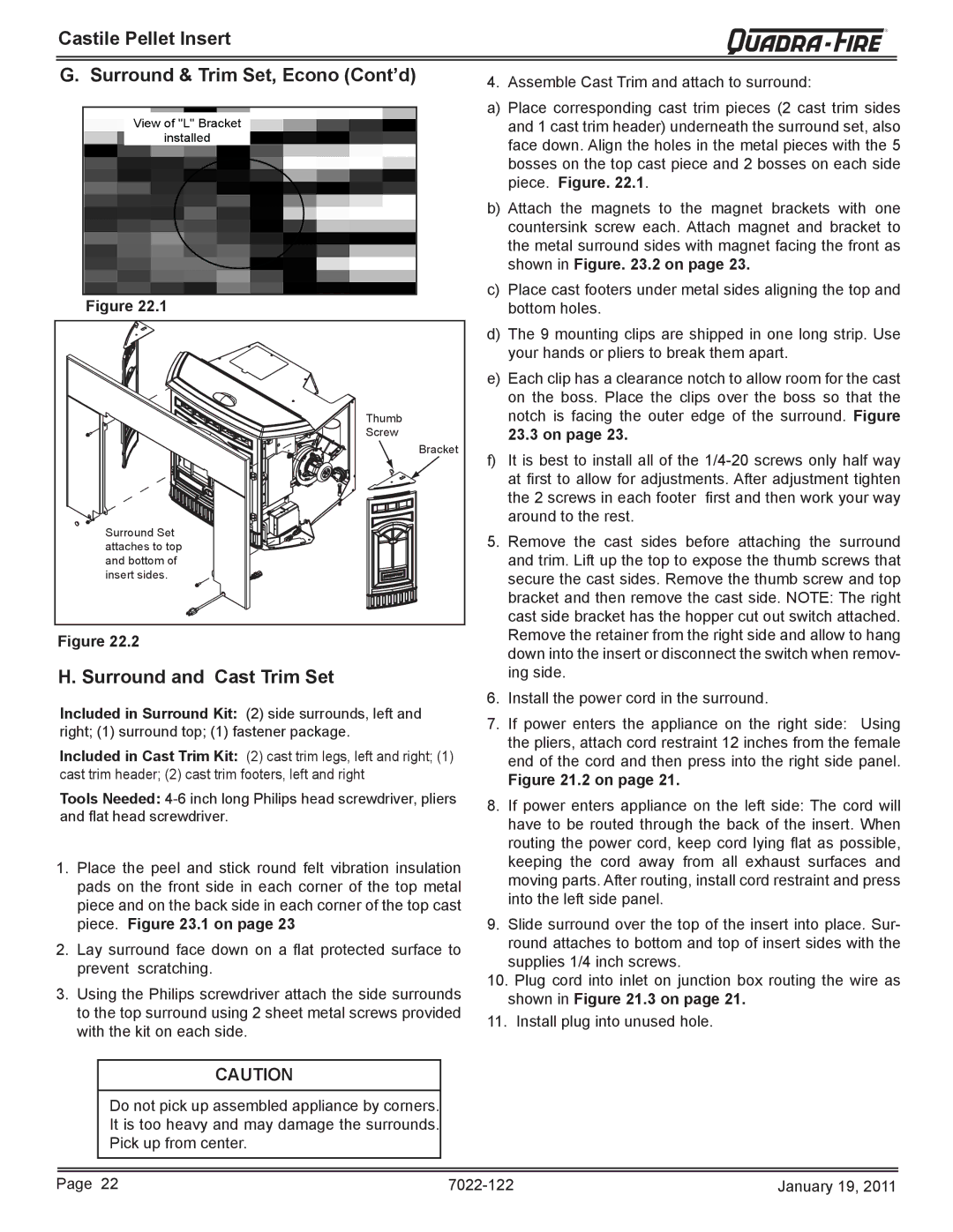
| Figure 22.1 | bottom holes. | |||
Thumb |
Screw |
Bracket |
Surround Set |
attaches to top |
and bottom of |
insert sides. |
Figure 22.2
H. Surround and Cast Trim Set
Included in Surround Kit: (2) side surrounds, left and right; (1) surround top; (1) fastener package.
Included in Cast Trim Kit: (2) cast trim legs, left and right; (1) cast trim header; (2) cast trim footers, left and right
Tools Needed:
1.Place the peel and stick round felt vibration insulation pads on the front side in each corner of the top metal piece and on the back side in each corner of the top cast piece. Figure 23.1 on page 23
2.Lay surround face down on a fl at protected surface to prevent scratching.
3.Using the Philips screwdriver attach the side surrounds to the top surround using 2 sheet metal screws provided with the kit on each side.
d)The 9 mounting clips are shipped in one long strip. Use your hands or pliers to break them apart.
e)Each clip has a clearance notch to allow room for the cast on the boss. Place the clips over the boss so that the notch is facing the outer edge of the surround. Figure 23.3 on page 23.
f)It is best to install all of the
5.Remove the cast sides before attaching the surround and trim. Lift up the top to expose the thumb screws that secure the cast sides. Remove the thumb screw and top bracket and then remove the cast side. NOTE: The right cast side bracket has the hopper cut out switch attached. Remove the retainer from the right side and allow to hang down into the insert or disconnect the switch when remov- ing side.
6.Install the power cord in the surround.
7.If power enters the appliance on the right side: Using the pliers, attach cord restraint 12 inches from the female end of the cord and then press into the right side panel.
Figure 21.2 on page 21.
8.If power enters appliance on the left side: The cord will have to be routed through the back of the insert. When routing the power cord, keep cord lying fl at as possible, keeping the cord away from all exhaust surfaces and moving parts. After routing, install cord restraint and press into the left side panel.
9.Slide surround over the top of the insert into place. Sur- round attaches to bottom and top of insert sides with the supplies 1/4 inch screws.
10.Plug cord into inlet on junction box routing the wire as shown in Figure 21.3 on page 21.
11.Install plug into unused hole.
CAUTION
Do not pick up assembled appliance by corners.
It is too heavy and may damage the surrounds.
Pick up from center.
Page 22 | January 19, 2011 |