R
Castile Pellet Insert
I. Baffle & Brick Set Removal
1.Follow proper shutdown procedures in Section 10.
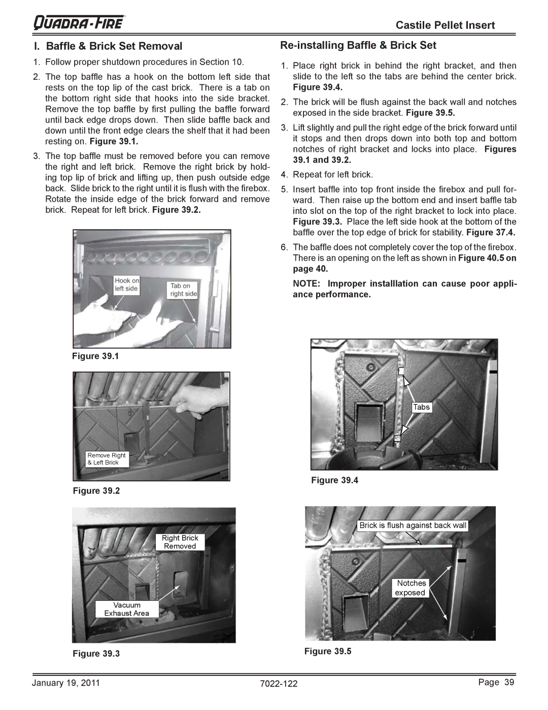
2.The top baffl e has a hook on the bottom left side that rests on the top lip of the cast brick. There is a tab on the bottom right side that hooks into the side bracket. Remove the top baffl e by fi rst pulling the baffl e forward until back edge drops down. Then slide baffl e back and down until the front edge clears the shelf that it had been resting on. Figure 39.1.
3.The top baffl e must be removed before you can remove the right and left brick. Remove the right brick by hold- ing top lip of brick and lifting up, then push outside edge back. Slide brick to the right until it is fl ush with the fi rebox. Rotate the inside edge of the brick forward and remove brick. Repeat for left brick. Figure 39.2.
Re-installing Baffle & Brick Set
1.Place right brick in behind the right bracket, and then slide to the left so the tabs are behind the center brick.
Figure 39.4.
2.The brick will be fl ush against the back wall and notches exposed in the side bracket. Figure 39.5.
3.Lift slightly and pull the right edge of the brick forward until it stops and then drops down into both top and bottom notches of right bracket and locks into place. Figures 39.1 and 39.2.
4.Repeat for left brick.
5.Insert baffl e into top front inside the fi rebox and pull for- ward. Then raise up the bottom end and insert baffl e tab into slot on the top of the right bracket to lock into place. Figure 39.3. Place the left side hook at the bottom of the baffl e over the top edge of brick for stability. Figure 37.4.
6.The baffl e does not completely cover the top of the fi rebox. There is an opening on the left as shown in Figure 40.5 on page 40.
NOTE: Improper installlation can cause poor appli- ance performance.
Figure 39.1
Remove Right & Left Brick
Figure 39.2
Tabs
Figure 39.4
Brick is flush against back wall
Right Brick
Removed
Notches exposed
Vacuum
Exhaust Area
Figure 39.3 |
| Figure 39.5 |
|
|
|
|
|
|
January 19, 2011 | Page 39 |