Operation
6 Operation
Once you have the optical head and electronics housing positioned and connected properly, the system is ready for continuous operation.
The operation of the sensor can be done by means of the control panel in the electronics housing or by means of the software that came with your sensor.
6.1 Control Panel
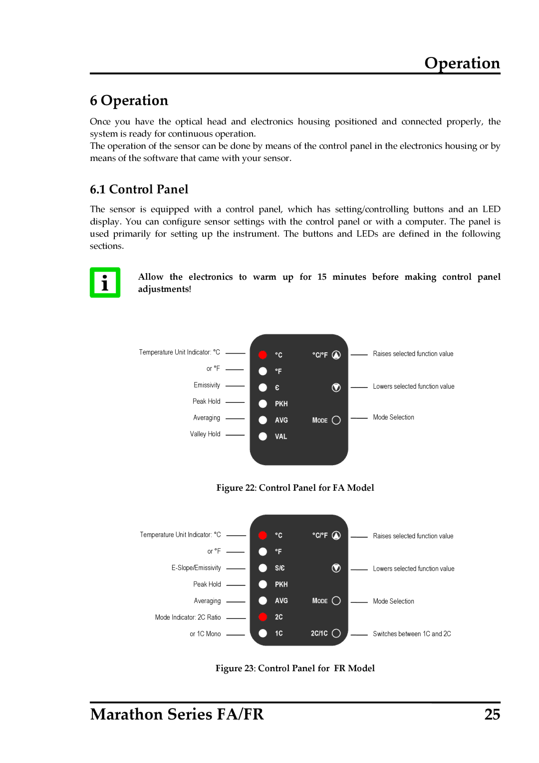
The sensor is equipped with a control panel, which has setting/controlling buttons and an LED display. You can configure sensor settings with the control panel or with a computer. The panel is used primarily for setting up the instrument. The buttons and LEDs are defined in the following sections.
Allow the electronics to warm up for 15 minutes before making control panel adjustments!
Temperature Unit Indicator: °C |
|
| °C | °C/°F |
| Raises selected function value |
|
| |||||
|
|
| ||||
or °F |
|
| °F |
|
|
|
|
|
|
|
| ||
|
|
|
|
|
| |
Emissivity |
|
| Є |
|
| Lowers selected function value |
|
|
| ||||
|
|
|
| |||
Peak Hold |
|
| PKH |
|
|
|
|
|
|
|
| ||
|
|
|
|
|
| |
Averaging |
|
| AVG | MODE |
| Mode Selection |
|
|
| ||||
|
|
|
|
| ||
Valley Hold |
|
| VAL |
|
|
|
|
|
|
|
| ||
|
|
|
|
|
|
Figure 22: Control Panel for FA Model
Temperature Unit Indicator: °C |
|
| °C | °C/°F | Raises selected function value | |
|
| |||||
or °F |
|
|
| °F |
|
|
|
|
|
|
| ||
|
|
| S/Є |
| Lowers selected function value | |
|
|
|
| |||
Peak Hold |
|
|
| PKH |
|
|
|
|
|
|
| ||
Averaging |
|
|
| AVG | MODE | Mode Selection |
|
|
| ||||
Mode Indicator: 2C Ratio |
|
|
| 2C |
|
|
|
|
|
|
| ||
or 1C Mono |
|
|
| 1C | 2C/1C | Switches between 1C and 2C |
|
|
| ||||
Figure 23: Control Panel for FR Model
Marathon Series FA/FR | 25 |