Programming Guide
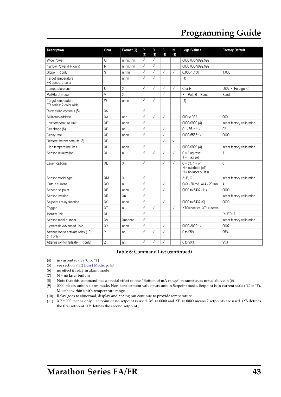
Description | Char | Format (2) | P | B | S | N | Legal Values | Factory Default |
|
|
| (1) | (1) | (1) | (1) |
|
|
Wide Power | Q | nnnn.nnn | √ | √ |
|
|
| |
Narrow Power (FR only) | R | nnnn.nnn | √ | √ |
|
|
| |
Slope (FR only) | S | n.nnn | √ | √ | √ | √ | 1.000 | |
Target temperature | T | nnnn | √ | √ |
|
| (4) |
|
FR series: |
|
|
|
|
|
|
|
|
Temperature unit | U | X | √ | √ | √ | √ | C or F | USA: F, Foreign: C |
Poll/Burst mode | V | X |
|
| √ |
| P = Poll, B = Burst | Burst |
Target temperature | W | nnnn | √ | √ |
|
| (4) |
|
FR series: |
|
|
|
|
|
|
|
|
Burst string contents (5) | X$ |
| √ |
|
|
|
|
|
Multidrop address | XA | nnn | √ | √ | √ |
| 000 to 032 | 000 |
Low temperature limit | XB | nnnn | √ |
|
|
| set at factory calibration | |
Deadband (6) | XD | nn | √ |
| √ |
| 01 - 55 in °C | 02 |
Decay rate | XE | nnnn | √ |
| √ |
| 0000 | |
Restore factory defaults (8) | XF |
|
|
| √ | √ |
|
|
High temperature limit | XH | nnnn | √ |
|
|
| set at factory calibration | |
Sensor initialization | XI | n | √ | √ | √ | √ | 0 = Flag reset | 1 |
|
|
|
|
|
|
| 1 = Flag set |
|
Laser (optional) | XL | X | √ |
| √ | √ | 0 = off, 1 = on | 0 |
|
|
|
|
|
|
| H = overheat (off) |
|
|
|
|
|
|
|
| N = no laser built in |
|
Sensor model type | XM | X | √ |
|
|
| A, B, C | set at factory calibration |
Output current | XO | n | √ |
| √ |
| 0=0 - 20 mA, 4=4 - 20 mA | 4 |
Second setpoint | XP | nnnn | √ |
| √ |
| 0000 to 5432 (11) | 0000 |
Sensor revision | XR | Xn | √ |
|
|
|
| set at factory calibration |
Setpoint / relay function | XS | nnnn | √ |
| √ |
| 0000 to 5432 (9) | 0000 |
Trigger | XT | n | √ | √ |
| √ | XT0=inactive, XT1= active |
|
Identify unit | XU |
| √ |
|
|
|
| !XUFR1A |
Sensor serial number | XV | Xnnnnnn | √ |
|
|
|
| set at factory calibration |
Hysteresis Advanced Hold | XY | nnnn | √ |
| √ |
| 0002 | |
Attenuation to activate relay (10) | Y | nn | √ | √ | √ |
| 0 to 95% | 95% |
(FR only) |
|
|
|
|
|
|
|
|
Attenuation for failsafe (FR only) | Z | nn | √ | √ | √ |
| 0 to 99% | 95% |
Table 6: Command List (continued)
(4)in current scale (°C or °F)
(5)see section 9.3.2 Burst Mode, p. 40
(6)no effect if relay in alarm mode
(7)N = no laser built in
(8)Note that this command has a special effect on the “Bottom of mA range” parameter, as noted above in (6)
(9)0000 places unit in alarm mode. Non‐zero setpoint value puts unit in Setpoint mode. Setpoint is in current scale (°C or °F). Must be within unit’s temperature range.
(10)Relay goes to abnormal, display and analog out continue to provide temperature.
(11)XP = 000 means only 1 setpoint or no setpoint is used. XS <> 0000 and XP <> 0000 means 2 setpoints are used. (XS defines the first setpoint. XP defines the second setpoint.)
Marathon Series FA/FR | 43 |