Controls and Functions
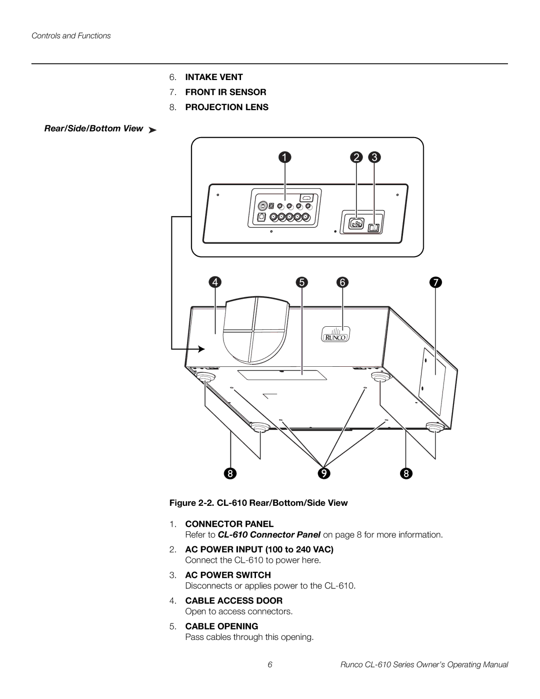
6.INTAKE VENT
7.FRONT IR SENSOR
8.PROJECTION LENS
Rear/Side/Bottom View ➤
Figure 2-2. CL-610 Rear/Bottom/Side View
1.CONNECTOR PANEL
Refer to
2.AC POWER INPUT (100 to 240 VAC) Connect the
3.AC POWER SWITCH
Disconnects or applies power to the
4.CABLE ACCESS DOOR Open to access connectors.
5.CABLE OPENING
Pass cables through this opening.
6 | Runco |
